Optical imaging system and optical imaging detection method

a technology of optical imaging and detection method, which is applied in the field of optical imaging system and optical imaging detection method, can solve the problems of little general purpose of optical imaging system, time-consuming detection, and adjustment, and achieve the effect of easy control of system and display of images suitable for the probe therewith

Inactive Publication Date: 2006-07-04
OLYMPUS CORP
View PDF8 Cites 29 Cited by
  • Summary
  • Abstract
  • Description
  • Claims
  • Application Information

AI Technical Summary

Problems solved by technology

Detection, discernment, and adjustment are time-consuming.
The optical imaging system is therefore of little general-purpose.
When an optical scanner probe other than a three-dimensional optical scanner probe is used in combination, it is hard to control the system and display images suitable to the probe therewith.
Thus, the optical imaging system has low adaptability.
Moreover, in the above system, it is hard to find a focal point at which a resolution of a displayed tomographic image is the highest.
It therefore takes too much time to achieve diagnosis.
In particular, when a plurality of types of optical probes are employed, since the focal points of the optical probes are different from one another, it is very hard to find where is the focal point of an optical probe.
Furthermore, the conventional optical imaging systems have not taken measures to obviate the necessity of correcting an individual difference of an optical probe that is freely detachably attached to a main body.
Furthermore, the conventional optical imaging systems include a scanning means that includes a scanner but do not attempt to control an image producing means using information, which is acquired by the scanning means, in consideration of the characteristics of an optical probe.
Gain control is therefore labor-intensive.
Attending to gamma control is labor-intensive.
However, the optical imaging system described in the Japanese Unexamined Patent Application Publication No. 2000-75210 does not provide measures against the conditions for driving the scanners, the details of an operating procedure, and imaging.

Method used


Image

  • Optical imaging system and optical imaging detection method
  • Optical imaging system and optical imaging detection method
  • Optical imaging system and optical imaging detection method

Examples


first embodiment

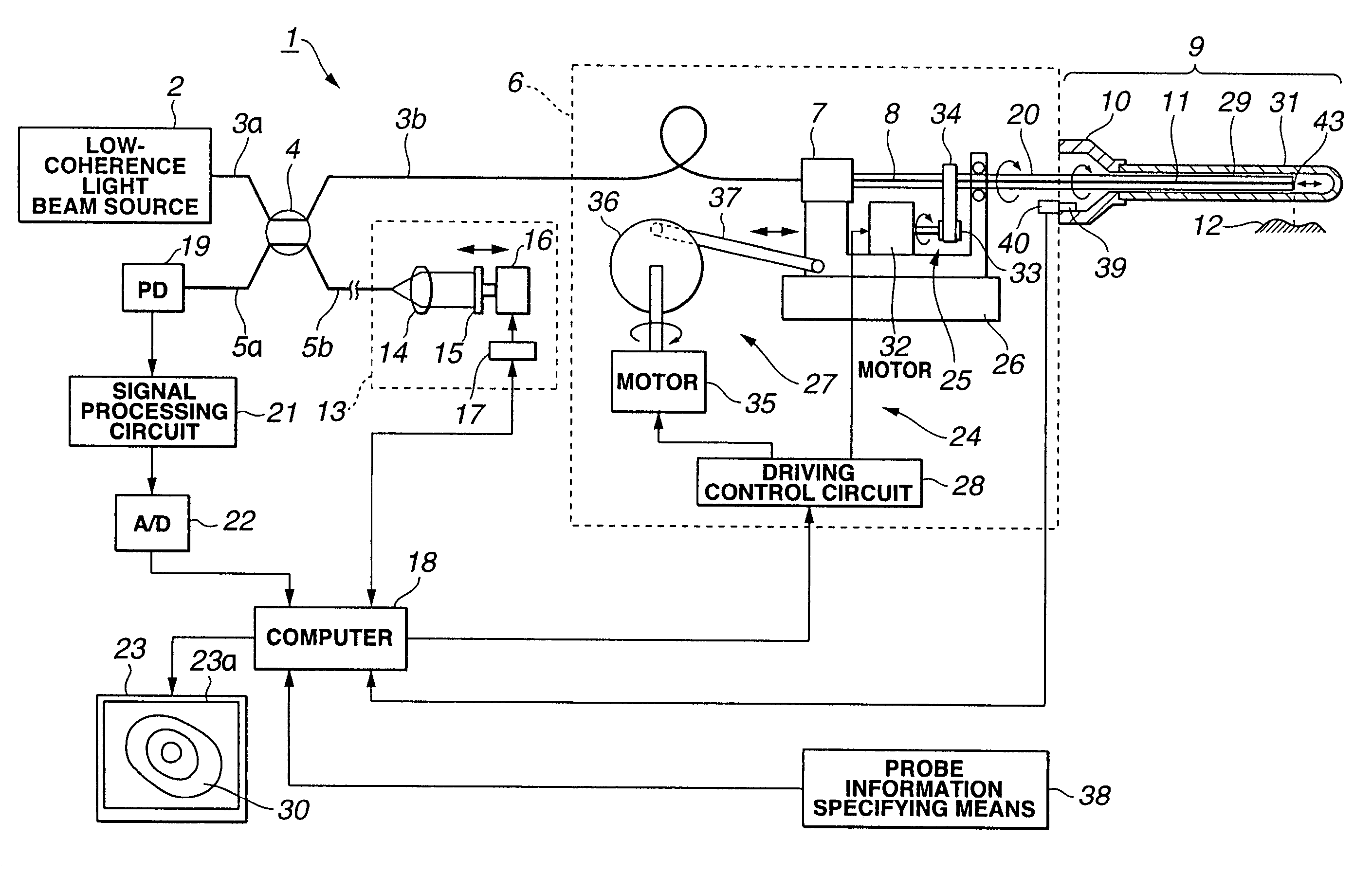
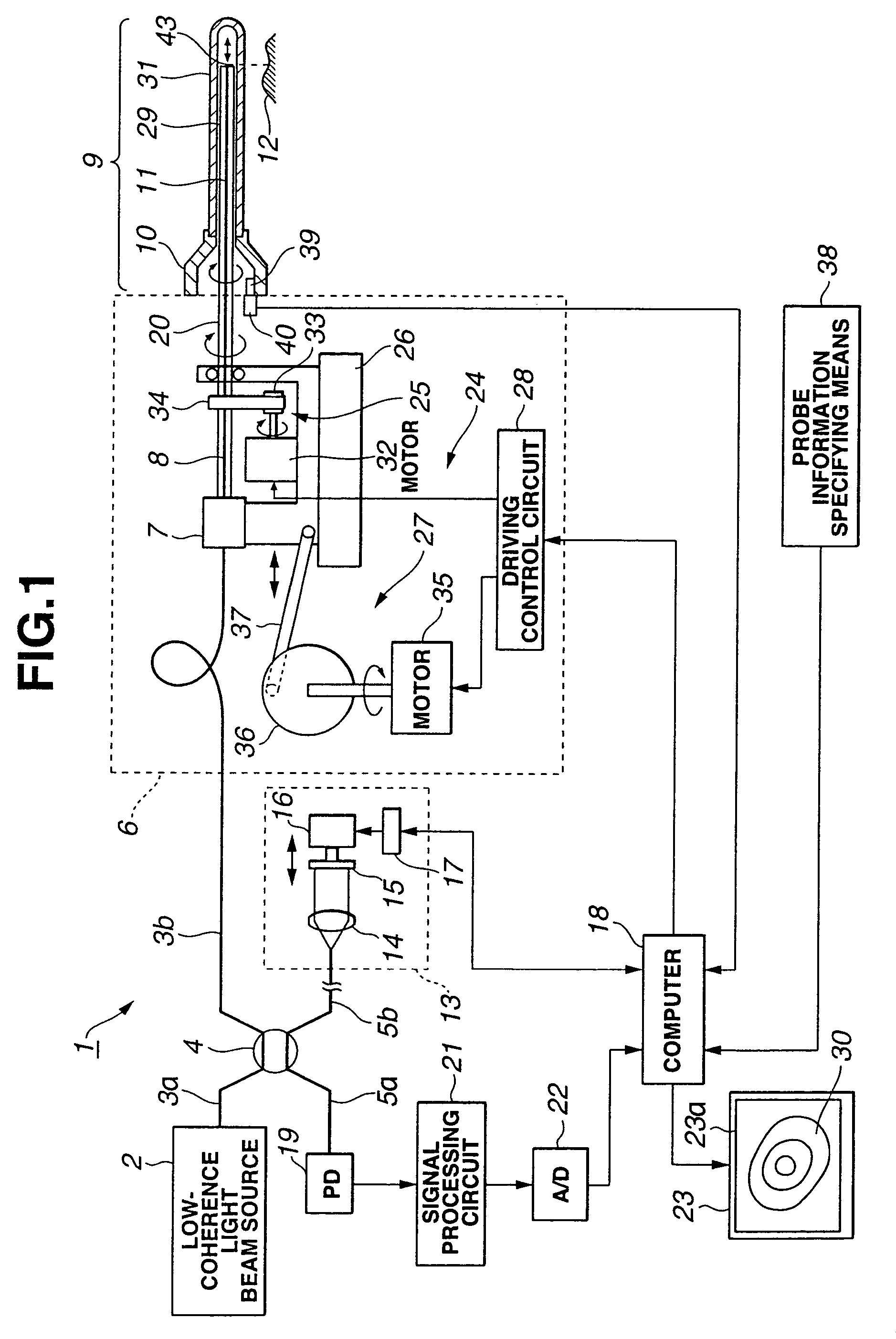
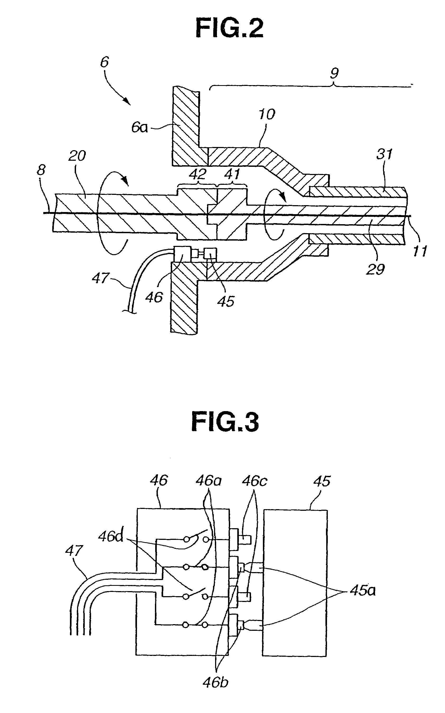
[0096]FIG. 1 to FIG. 19 are concerned with a first embodiment of the present invention. FIG. 1 shows the configuration of an optical imaging system in accordance with the first embodiment. FIG. 2 shows the structure of a micro-switch-inclusive probe information detecting mechanism included in the optical imaging system shown in FIG. 1. FIG. 3 is an explanatory diagram concerning the principles of operation based on a micro-switch-inclusive detecting method implemented in the mechanism shown in FIG. 2. FIG. 4 is a flowchart describing a procedure for detecting and processing probe information. FIG. 5 is a flowchart detailing the probe information detecting procedure mentioned in FIG. 4. FIG. 6 is a flowchart describing a procedure of adjusting and controlling an optical system included in the procedure mentioned in FIG. 4. FIG. 7 is a flowchart describing a procedure of driving and controlling a probe according to a scanning technique implemented in the probe, a procedure of imaging,...

second embodiment

[0188]A second embodiment of the present invention will be described below.

[0189]FIG. 20 to FIG. 22 show a major portion of the second embodiment of the present invention. A photo-sensor assemblage 85 is used as a probe information detecting means, which is disposed in both the joint members included in the optical probe 9 and observing device 6 respectively, in place of a micro-switch-inclusive probe detecting means employed in the first embodiment.

[0190]The photo-sensor assemblage 85 composed of a plurality of photo-sensors is incorporated in the joint member 6a included in the observing device 6. Specifically, the photo-sensor assemblage 85 includes a light-emitting element plate 87a on which a plurality of light-emitting elements 86a is mounted, and a light-receiving element plate 87b on which a plurality of light-receiving elements 86b is mounted to face the plurality of light-emitting elements 86a.

[0191]Moreover, a light interceptor 88 is included in the attachment 10 of the ...

third embodiment

[0200]FIG. 23 and FIG. 24 show a major portion of a third embodiment of the present invention. In this embodiment, a memory module 93 is adopted as a probe information detecting means that links both the joint members included in the optical probe 9 and observing device 6 respectively.

[0201]The memory module 93 is incorporated inside the attachment 10 of the optical probe 9, and connected to a cable connector 95 disposed in the joint member 6a of the observing device 6 through memory connector members 94a connected to the memory module 93.

[0202]The memory connector members 94a have pins thereof coupled to a power line or signal lines, and are connected to the computer 18 over a cable 96 that is coupled to pin receptacles included in the cable connector 95.

[0203]Power required by the memory module 93 is supplied from the computer 18 over the power line. Probe information recorded in advance in the memory module 93 is in turn read into the computer 18 over the signal lines.

[0204]FIG. ...


PUM

PropertyMeasurementUnit
coherence lengthaaaaaaaaaa
distanceaaaaaaaaaa

Abstract

An attachment 10 that is proximal to an optical probe 9 includes probe information holding means 39 that holds probe information such as a scanning technique and an optical path length or the like. When the optical probe 9 is connected (attached) to an observing device 6, probe information detecting means included in the observing device 6 automatically detects the probe information held in the optical probe. Based on the detected probe information, a scanning technique and an optical path length of reference light are set to values suitable to an actually connected optical probe 9.

Description

[0001]The present application is a continuation application of International PCT Application No. PCT / JP02 / 04385 filed May 2, 2002 to which priority is being asserted.TECHNICAL FIELD[0002]The present invention relates to an optical imaging system and an optical imaging detection method for irradiating a low coherence light beam to an object and constructing a tomographic image of the inside of the object from information of light scattered or reflected from the object.BACKGROUND ART[0003]Arts related to optical imaging systems include, for example, the one described in Japanese Unexamined Patent Application Publication No. 11-148897. As one type of optical imaging system, an optical imaging system referred to as an optical coherence tomography system is known. The optical coherence tomography system has an optical probe that is inserted into a human body and that has a light receiving / emitting means incorporated in the distal part thereof. The light receiving / emitting means emits low...

Claims


Application Information

Patent Timeline
Patent Type & Authority Patents(United States)
IPC IPC(8): G01B9/02A61B1/00A61B5/00A61B10/00G01B11/24G01N21/17
CPCA61B5/0066A61B5/6852A61B2562/08
Inventor XIE, TIANYUUCHIYAMA, AKIOOKAWA, ATSUSHI
Owner OLYMPUS CORP
Why Eureka
Try Eureka