
Optical detection and microimaging method of micro-nano particles not subjected to influence of background

A microscopic imaging and optical detection technology, applied in the analysis of materials, instruments, etc., can solve the problems of submerging small particle signals, difficulty in detecting non-metallic material particles, and little change in refractive index

Active Publication Date: 2014-09-03
DALIAN UNIV OF TECH
View PDF3 Cites 17 Cited by
  • Summary
  • Abstract
  • Description
  • Claims
  • Application Information

AI Technical Summary

Problems solved by technology

[0004] Compared with gold nanoparticles, the detection of ordinary non-metallic material particles is more difficult: 1) The refractive index does not change much with respect to the medium environment; 2) The scattering signal generated by the large particles in the background will completely submerge the small particles Signal
However, existing technologies cannot solve this problem

Method used


Image

  • Optical detection and microimaging method of micro-nano particles not subjected to influence of background
  • Optical detection and microimaging method of micro-nano particles not subjected to influence of background
  • Optical detection and microimaging method of micro-nano particles not subjected to influence of background

Examples


Embodiment Construction

[0022] The preferred embodiments will be described in detail below in conjunction with the accompanying drawings. It should be emphasized that the following description is only exemplary and not intended to limit the scope of the invention and its application.

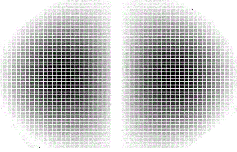
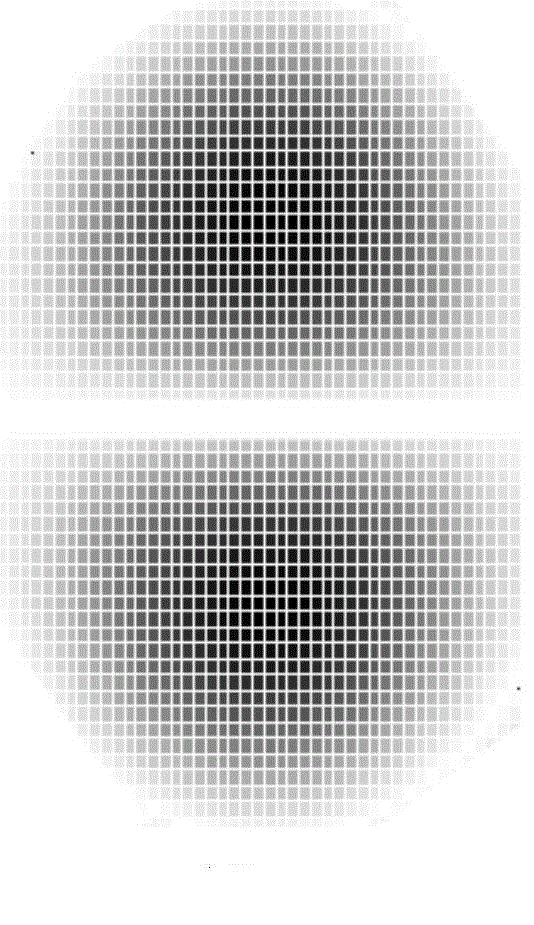
[0023] The purpose of the invention is to detect and image micro-nano particles in the environment noise where large particles exist, and proposes an optical detection and micro-imaging method for micro-nano particles that are not affected by the background.

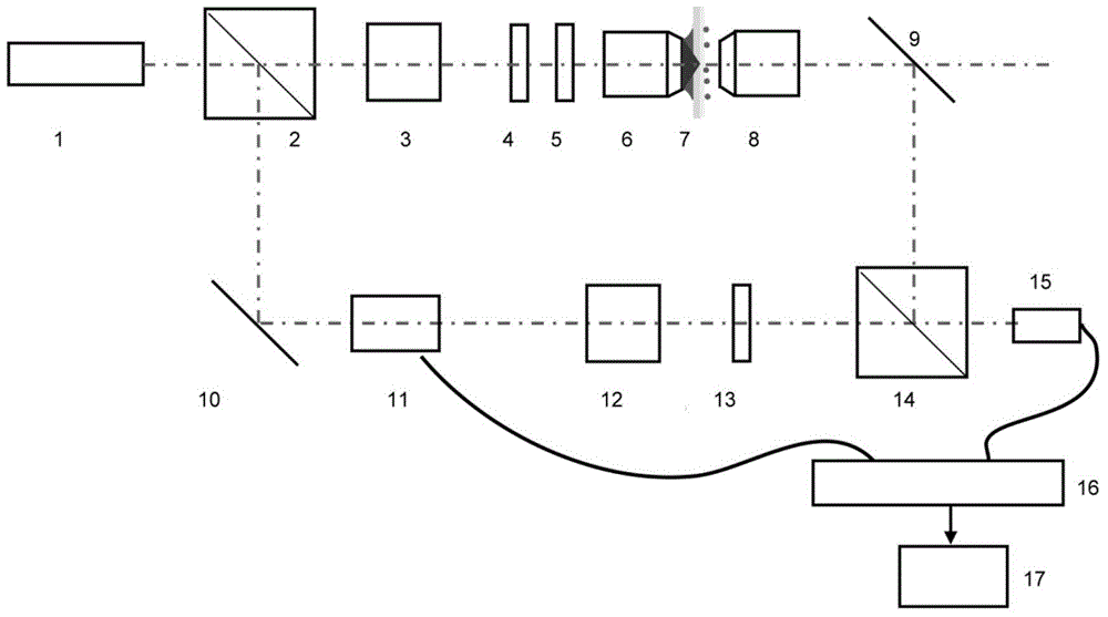
[0024] The method of the present invention is applied to a laser polarization heterodyne interference microscopic measurement device, which device includes a laser 1, a beam splitter 2, a beam expander 3, a beam expander 4, a polarization adjustment device 5, a polarization adjustment device 6, and an oil-immersion / water-immersion objective lens 7 , plated glass sheet 8, objective lens 9, mirror 10, acousto-optic modulator device 11, common beam splitting prism 1...


PUM

PropertyMeasurementUnit
thicknessaaaaaaaaaa
diameteraaaaaaaaaa
diameteraaaaaaaaaa

Abstract

The invention discloses an optical detection and microimaging method of micro-nano particles not subjected to the influence of the background. The diameter range of the micro-nano particles is 10nm to 400nm. The method is characterized in that an oil-immersed microobjective with high numerical aperture is used for exciting surface plasma resonance of a precious metal / medium interface, a light field in a focus plane is scattered through the micro-nano particles, is collected by another microobjective to be used as signal light which is subjected to polarized heterodyne interference together with reference light, the amplitude and the phase of longitudinal polarized state of transmitting light are extracted so as to detect and image the micro-nano particles. By controlling the exciting condition of the surface plasma, the particles with the diameter being greater than 400nm do not produce the surface plasma resonance under the excitation, so that the large-particle background is removed, and the micro-nano particles can be detected and imaged in the background with the existence of the large particles.

Description

technical field [0001] The invention belongs to the technical field of laser heterodyne measurement, and relates to an optical detection and microscopic imaging method of micro-nano particles not affected by the background. Background technique [0002] It is a great challenge to detect sub-wavelength and below-sized micro-nano particles with optical methods, because according to the Rayleigh scattering theory, the scattering intensity of particles is proportional to the diameter of particles, for example, when the diameter of particles decreases from 200nm to When it reaches 5nm, its scattered light intensity will decrease rapidly by 4.1*10 9 times. In addition, due to the small scattering cross-section of the nano-object, when it is irradiated with light, only a very small part of the incident light can be incident on it, and most of the incident light becomes the background noise. In order to improve the signal-to-noise ratio, it is natural to think of focusing light ef...

Claims


Application Information

Patent Timeline
Patent Type & Authority Applications(China)
IPC IPC(8): G01N15/00
Inventor 洪昕邱天爽
Owner DALIAN UNIV OF TECH
Learn More