Non-contact photoacoustic detecting method and device based on optical interferometry

An optical interference and non-contact technology, which is applied in the generation of ultrasonic/sonic/infrasonic waves, and the use of sound waves/ultrasonic/infrasonic waves to analyze fluids, etc. It can solve the problems affecting imaging stability and repeatability, PAI application range limitations, and imaging cannot be performed, etc. problem, to achieve the effect of improving system sensitivity, high sensitivity, improving stability and repeatability

Inactive Publication Date: 2016-02-17
NORTHEASTERN UNIV
View PDF5 Cites 20 Cited by
  • Summary
  • Abstract
  • Description
  • Claims
  • Application Information

AI Technical Summary

Problems solved by technology

This method is extremely inconvenient to operate and lacks practicability, resulting in the inability to perform many imaging operations due to the inability to perform acoustic coupling.
At the same time, the degree of contact between the membrane and the sample also has a greater impact on the imaging results, thus affecting the stability and repeatability of the imaging
At present, there are still photoacoustic signal detection using thin-film F-P interferometer and optical fiber as pressure sensor. Although these two methods

Method used


Image

  • Non-contact photoacoustic detecting method and device based on optical interferometry

Examples


Embodiment 1

[0032] A non-contact photoacoustic detection method based on optical interferometry, comprising the following steps:

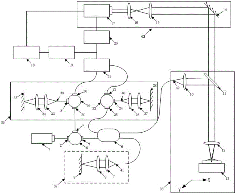
[0033] S1. Photoacoustic excitation: a liquid layer is added to the surface of the sample, and the sample is irradiated by the photoacoustic excitation system. The sample absorbs laser energy and generates pressure waves, which are transmitted to the liquid, causing the liquid surface to vibrate;

[0034] S2. Optical coherence detection: the light emitted by the coherent light source is divided into two paths, one path is used as the probe light to enter the sample system and then focused on the sample surface, and the other path is used as the reference light to enter the reference system. The two paths of light are the probe light reflected by the sample surface And the reference light reflected by the reference system returns along the original optical path, and is divided into two paths again to send out;

[0035] S3. Balance adjustment: In step S2, the li...

Embodiment 2

[0038] A non-contact photoacoustic detection method based on optical interferometry, comprising the following steps:

[0039] S1. Photoacoustic excitation: There is a liquid layer on the surface of the sample. The photoacoustic excitation light source in the photoacoustic excitation system emits laser light with a pulse width less than 10 ns to irradiate the sample. The sample absorbs the laser energy and generates pressure waves, which are transmitted to the liquid, making The surface of the liquid layer on the surface of the sample vibrates;

[0040] S2. Optical coherent detection: the light emitted by a coherent light source with a coherent length of 1mm enters the coupler through a circulator and is divided into two paths. One path is used as the probe light and enters the sample system and then focuses on the surface of the liquid layer on the sample surface. The other path is used as The reference light enters the reference system, and the two-way light, namely the probe...

Embodiment 3

[0044] A non-contact photoacoustic detection method based on optical interferometry, comprising the following steps:

[0045] S1. Photoacoustic excitation: There is a liquid layer on the surface of the sample. The photoacoustic excitation light source in the photoacoustic excitation system emits laser light with a pulse width less than 10 ns to irradiate the sample. The sample absorbs the laser energy and generates pressure waves, which are transmitted to the liquid, making The surface of the liquid layer on the surface of the sample vibrates;

[0046] S2. Optical coherent detection: the light emitted by a coherent light source with a coherent length of 1m is divided into two paths after entering the coupler through a circulator. The reference light enters the reference system, and the two-way light, namely the probe light reflected by the liquid layer on the sample surface and the reference light reflected by the reference system, returns along the original light path, enters...


PUM

PropertyMeasurementUnit
Coherence lengthaaaaaaaaaa

Abstract

The invention discloses a non-contact photoacoustic detecting method based on optical interferometry. The method comprises the following steps of S1, photoacoustic stimulation, S2, optical coherent detection, S3, balance adjustment and S4 detecting window locking. The invention further discloses a non-contact photoacoustic detecting device based on optical interferometry and used for achieving the method. According to the method, the problem that acoustic coupling media must be used in current photoacoustic imaging is solved, and the application range of photoacoustic imaging is widened. High sensitivity is achieved, light spots of probe light can be focused to the micrometer or submicron scale, and high lateral resolution is achieved. Optical detection is adopted, high-speed scanning is easy, and therefore imaging speed can be increased. Real-time detection is carried out to interfere with system sensitivity, balance adjustment is carried out on probe light intensity, and photoacoustic detection is carried out in the state of the highest system sensitivity. The non-contact photoacoustic detecting device based on optical interferometry is further provided, and the stability and repeatability of imaging can be effectively improved.

Description

technical field [0001] The invention relates to a non-contact photoacoustic detection method and device based on an optical interference method, and specifically belongs to the technical field of photoacoustic detection. Background technique [0002] Photoacoustic imaging (PAI) is a high-resolution, high-contrast three-dimensional imaging technology developed in recent years. Its imaging principle is the photoacoustic effect. Seconds) after the sample is irradiated, the sample will cause its own temperature rise due to the absorption of light energy, and the temperature rise will cause the sample to thermally expand rapidly and generate ultrasonic waves, which is the process of photoacoustic effect. The ultrasonic waves excited by the photoacoustic effect will be transmitted to the surface of the sample, and the ultrasonic waves will be detected on the sample surface with a detector to obtain a photoacoustic signal, and the light absorption distribution of the sample will be...

Claims


Application Information

Patent Timeline
IPC IPC(8): G01N29/02G01N29/34
CPCG01N29/02G01N29/34
Inventor 王毅路交马振鹤
Owner NORTHEASTERN UNIV
Why Eureka
Try Eureka