
Light-weight high resolution viewer

a viewer and high-resolution technology, applied in the field of optical instruments, can solve the problems of increased “speed” of the lens, substantial chromatic aberration, poor image quality, etc., and achieve the effect of improving image quality and increasing magnification

Inactive Publication Date: 2006-07-04
THE KERR
View PDF25 Cites 16 Cited by
  • Summary
  • Abstract
  • Description
  • Claims
  • Application Information

AI Technical Summary

Benefits of technology

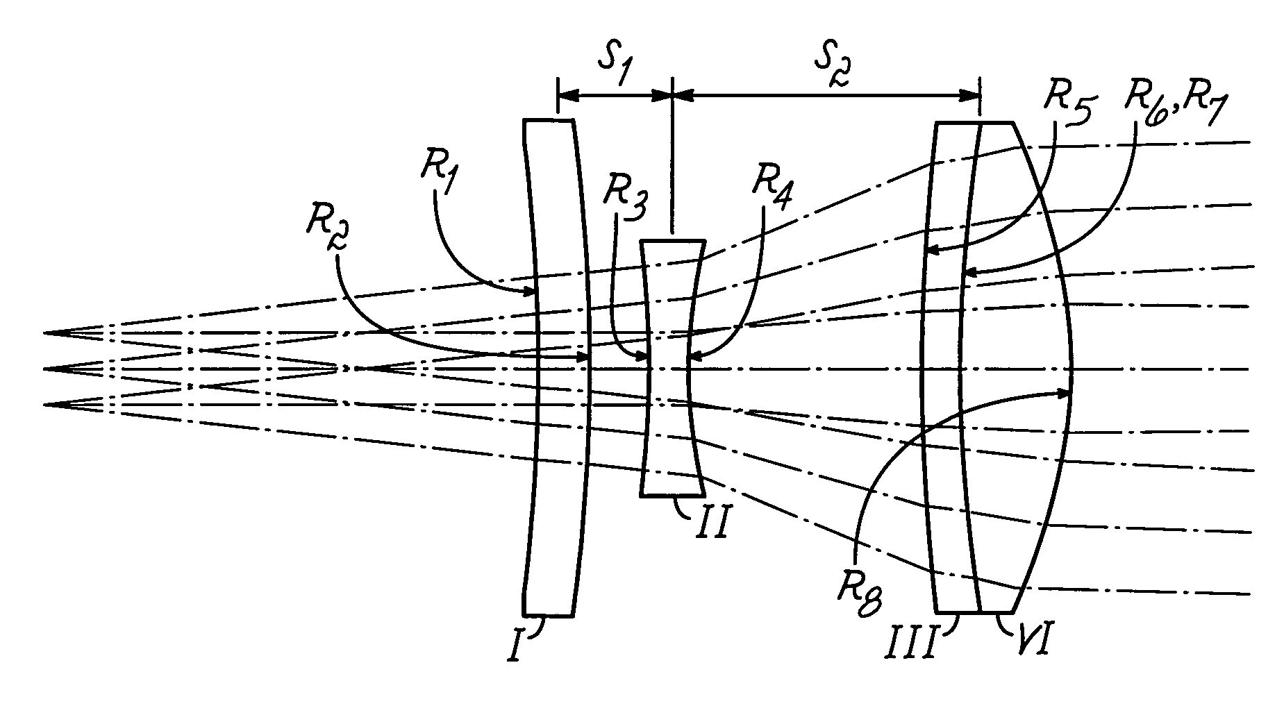
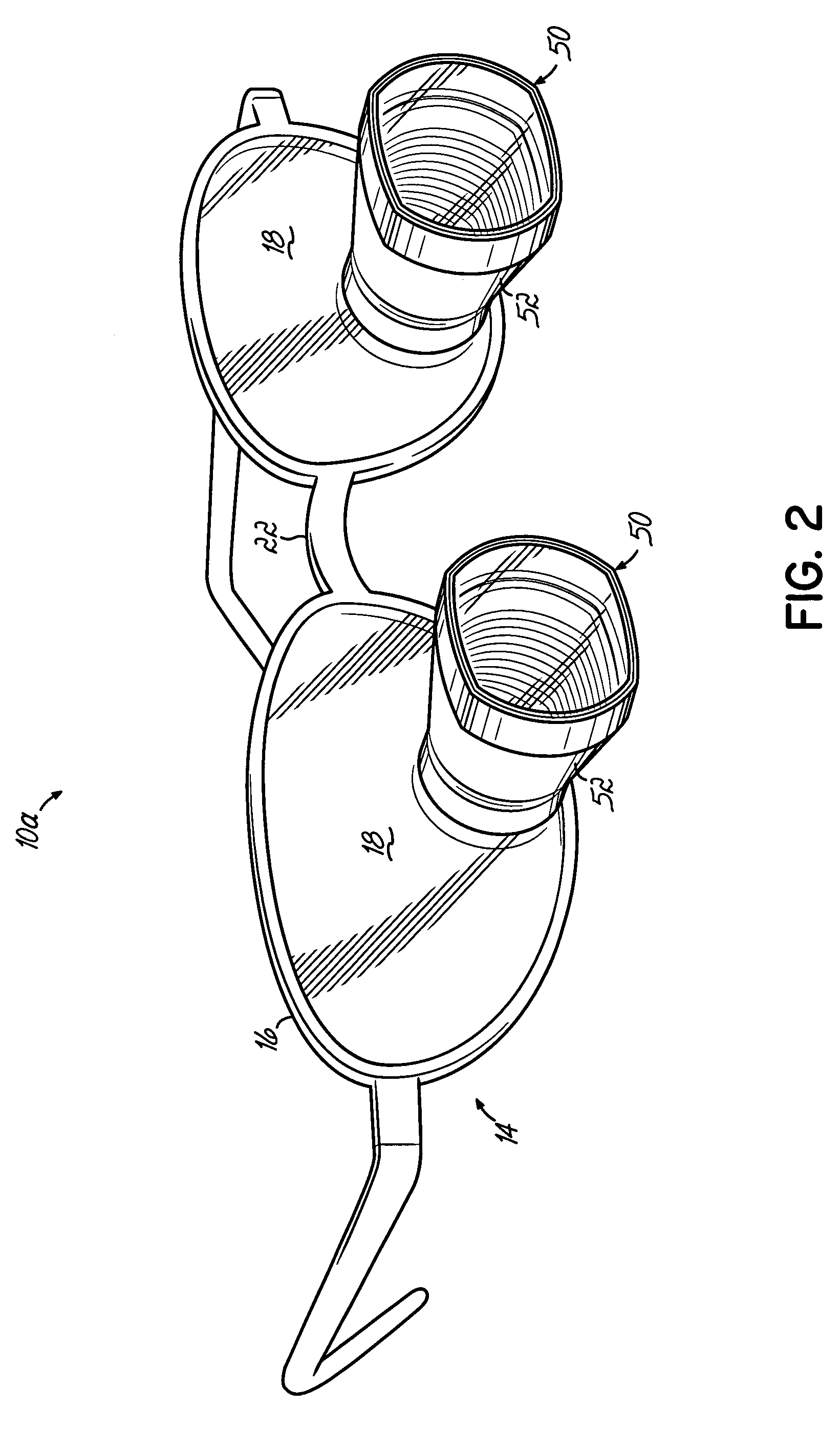
[0009]The present invention provides a magnification viewer having a lightweight magnification loupe providing increased magnification with an improved image quality. In an exemplary embodiment, the loupe includes a Galilean lens system, having a single-element eyepiece lens and a two-element objective lens. The loupe can be carried on a pair of eyeglasses, or other user wearable device, either by mounting to a flip-up mounting member secured to the bridge of the eyeglass frames, or by mounting through the eyeglass lenses.
[0010]In one aspect of the invention, the objective lens of the loupe has a non-circular shape, wherein adjacent pairs of oppositely disposed peripheral edges of the lens are defined by arcs having different length radii. The non-circular shape helps to minimize the weight of the loupe by reducing the overall size of the lenses while not adversely affecting the field of view. In one embodiment, a first pair of peripheral edges are defined by a first radius extending from the center of the lens, and a second pair of peripheral edges are defined by at least one second radius that extends from a point that is not coincident with the lens center. In another exemplary embodiment, the peripheral edges have a semi-elliptical shape, wherein the second pair of peripheral edges correspond to the periphery of an ellipse.
[0011]In another aspect of the invention, the loupe includes a correction lens that is removably mounted in the loupe housing. The correction lens can be removed from the housing and interchangeably replaced with a different correction lens to thereby vary the working distance of the loupe. Advantageously, the interchangeable correction lens allows the loupe to accommodate a range of working distances by selective replacement of a single element that is relatively inexpensive to manufacture. When the loupes are provided in a through-the-lens arrangement, the correction lens may be provided as a prescription lens to permit the loupes to be customized to a user's optical prescription.

Problems solved by technology

The basic Galilean design, however, produces substantial chromatic aberration (“coloring”) and, hence, poor image quality.
If this is done while keeping the focal length of the objective the same, the “speed” of the lens increases, resulting in a lower resolution quality.
It also mandates an excessively large package.
One method of overcoming the “speed” problem is to use a more complicated objective lens, though at a cost of greatly increased weight and, therefore increased strain and discomfort to the wearer.
While image quality is adequate at lower magnifications, excessive coloring results in poor image quality at higher magnifications.
Moreover, the field of view is relatively limited in Kellner lens systems.
It is known that image quality of prior art magnification viewers can be enhanced by the use of “very high index flint glass.” However, this method has not been in general use, since “very high index flint glass” generally makes the viewer too heavy for practical use.
As such, the manufacturing costs for these types of prior art viewers are relatively high.

Method used


Image

  • Light-weight high resolution viewer
  • Light-weight high resolution viewer
  • Light-weight high resolution viewer

Examples


Embodiment Construction

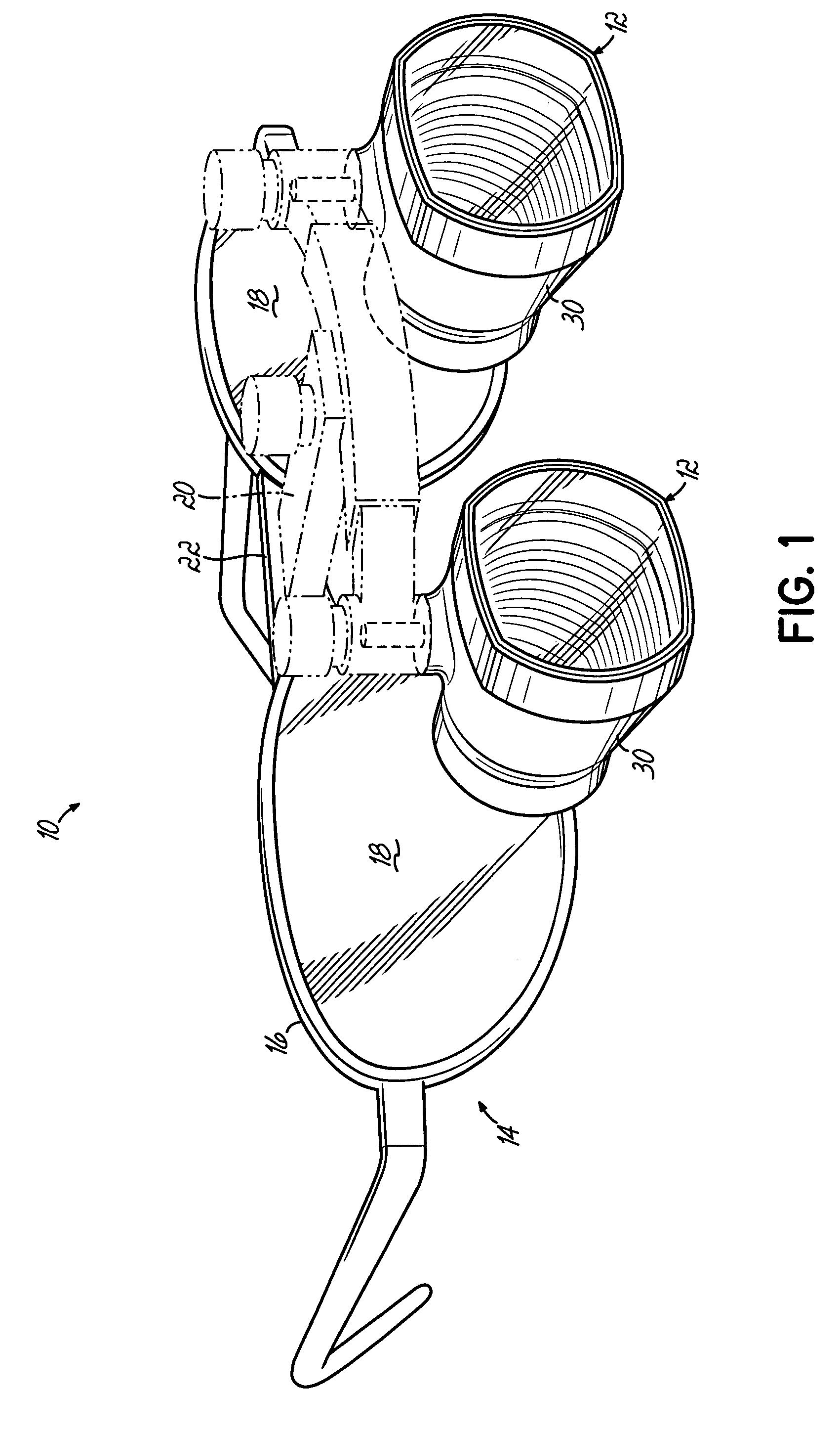
[0026]Referring to FIG. 1, there is shown a magnification viewer 10 having an exemplary magnification loupe 12 according to the present invention. The magnification viewer 10 comprises a pair of spectacles 14 having eyeglass frames 16 for supporting a pair of eyeglass lenses 18 as known in the art. The magnification viewer 10 further includes first and second magnification loupes 12 secured to the eyeglass frames 16 such as by a flip-up mounting member 20 coupled to a bridge 22 of the eyeglass frames 16. Advantageously, the loupes 12 may be pivoted by the mounting member 20 to be positioned in front of the respective eyeglass lenses 18 whereby a user may view a highly magnified image of an object positioned in front of the magnification viewers 10. Advantageously, the magnification loupes 12 are also pivotally secured to the flip-up mounting member 20 to permit adjustment of the convergence angle of the magnification viewer.

[0027]Referring now to FIGS. 3A and 5, the exemplary magnif...


PUM


Abstract

A magnification loupe carried by spectacles has a Galilean lens system comprising a single-element eyepiece lens and a two-element objective lens. The loupes may be mounted to eyeglass frames by a flip-up mounting member, or they may be mounted through the eyeglass lenses of the spectacles. The loupes provide high magnification while minimizing weight to thereby reduce strain and discomfort to users. In an exemplary embodiment, the objective lens has a non-circular shape that provides a wide field of view while further minimizing the weight of the loupe. A correction lens may be interchangeably coupled to the loupe housing to permit selective replacement with another correction lens to vary the working distance of the loupe.

Description

FIELD OF THE INVENTION[0001]The present invention relates generally to optical instruments, and more particularly to magnification viewers, such as those worn by surgeons and dentists.BACKGROUND OF THE INVENTION[0002]Magnification viewers are well known in the art and generally comprise one or more optical loupes coupled to eyeglass frames. These magnification viewers are often worn by dentists and surgeons for extended periods of time during clinical procedures so as to provide clarity of view while avoiding a “hunched over” position that can result in debilitating neck and back strain, and which can, in turn, have an adverse effect on the success of the operation. By permitting the clinician to operate at a greater working distance from the patient, higher magnification viewers also reduce the clinician's exposure to potential contamination from aerosols.[0003]Because clinicians use magnification viewers during surgery and other procedures requiring manual precision, it is importa...

Claims


Application Information

Patent Timeline
IPC IPC(8): G02B13/00G02C1/00A61C19/00G02B23/00G02B25/04G02C7/08
CPCG02B7/002G02C7/088G02B25/004G02B23/00
Inventor WILT, BRIAN L.SHIPLEY, PATRICK J.HOFFMAN, JEFFREY M.COTE, JASMIN
Owner THE KERR
Learn More