Method for recording information in optical information medium and reproducing information therefrom

a technology of optical information and recording information, which is applied in the field of recording information in optical information medium and reproducing information therefrom, can solve the problems of slow recording speed of recording unit and slow recording speed of reproducing unit, and the inability to improve recording speed, so as to achieve stable recording of recorded signals and high recording speed

Inactive Publication Date: 2006-07-04
KK TOSHIBA
View PDF18 Cites 16 Cited by
  • Summary
  • Abstract
  • Description
  • Claims
  • Application Information

AI Technical Summary

Benefits of technology

[0023]It is accordingly an object of the present invention to provide an optical head apparatus which is adapted for use with an optical information medium ensuring a high recording speed and enabling stable reproduction of recorded signals, and which is used for recording / reproducing operations.

Problems solved by technology

However, in the case of an optical recording / reproducing apparatus which is of a write-once type, the recording speed of the recording unit is slower than that the reproduction speed of the reproducing unit.
In general, optical beams of the same wavelength do not satisfy both the requirements of a recording beam and those of a reproducing beam.
With such a low absorption coefficient, the recording speed cannot be improved.
At the same time, however, the optical light does not produce a significant difference between the amount of light reflected from the recording pits and the amount of light reflected from the areas other than the recording pits.
Even this method, however, is restricted by the energy of a maximum output of a light source.
In the case where an information medium comprises an a recording layer having such a characteristic as is shown in FIG. 2, and information are recorded in the unrecorded areas of that recording layer, an optical beam that provides a high optical absorbing coefficient does not necessarily improve the recording speed.
In other words, the efficiency with which the energy is used is low at the start of the irradiation of the recording beam.
However, in the case where a recording beam having a wavelength that provides an absorbing coefficient of 50% or so is radiated onto the same unrecorded area, the absorbing coefficient does not increase.
Hence, the recording speed is not improved.
Accordingly, the adjustment needed for positioning the laser elements is hard to make and is thus costly.

Method used


Image

  • Method for recording information in optical information medium and reproducing information therefrom
  • Method for recording information in optical information medium and reproducing information therefrom
  • Method for recording information in optical information medium and reproducing information therefrom

Examples


Embodiment Construction

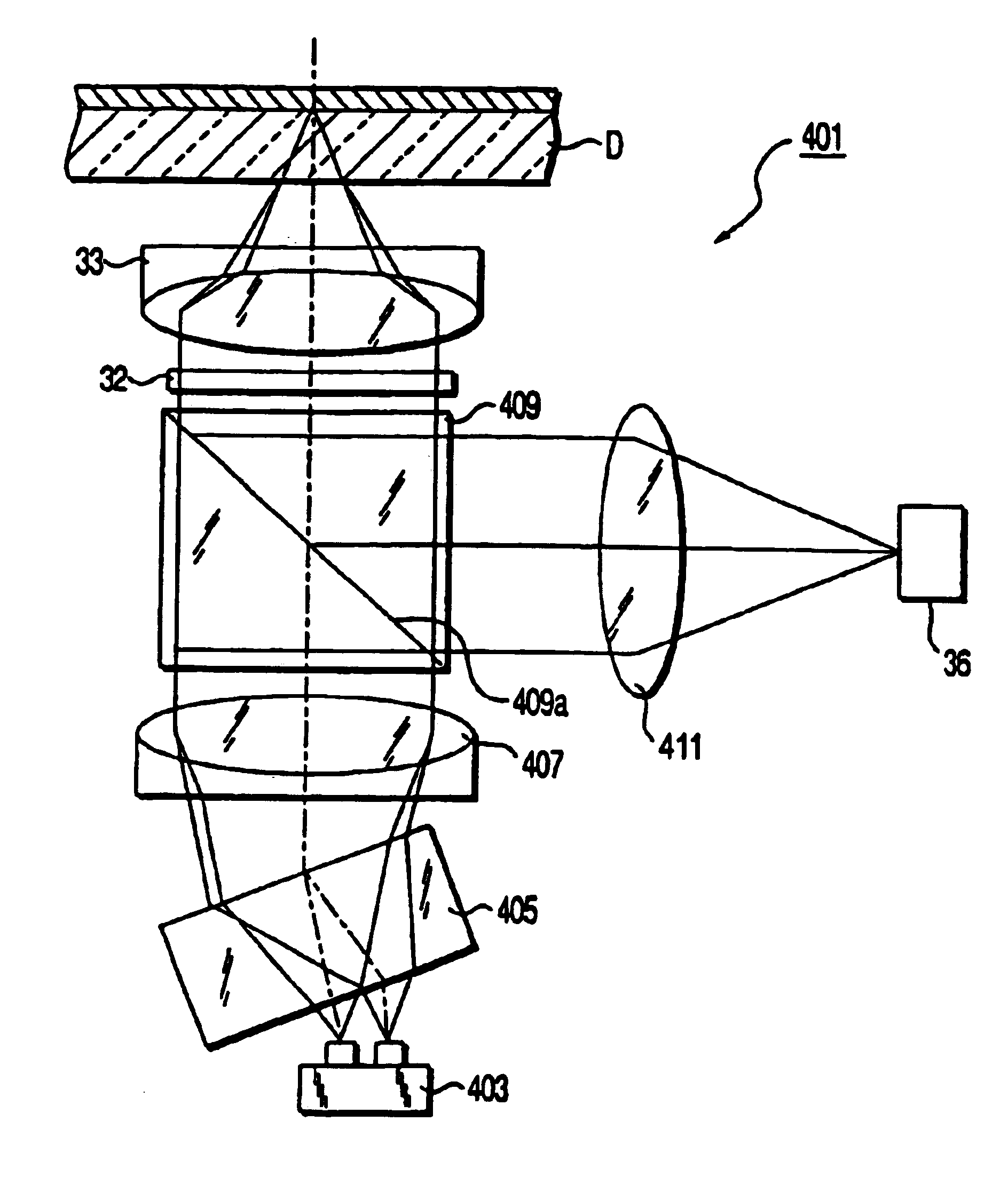
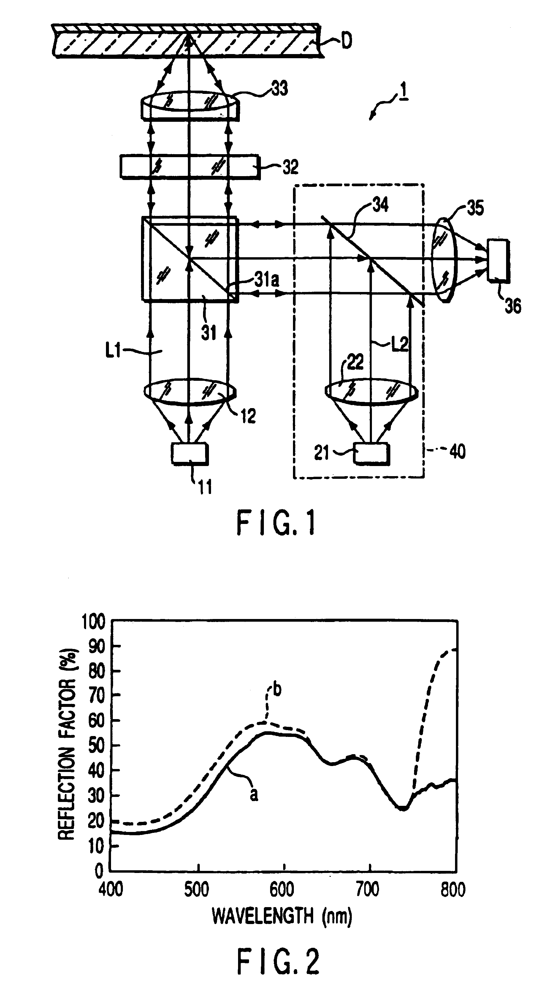
[0053]An optical head apparatus (i.e., an optical information recording / reproducing apparatus), which is one embodiment of the present invention and which records information in an optical information medium and reproduces information therefrom, will now be described with reference to the accompanying drawings, along with an information recording / reproducing method used in that apparatus.

[0054]As shown in FIG. 1, an optical head apparatus 1 comprises a first semiconductor element 11 for emitting a laser beam (optical beam) L1 having a first wavelength and a second semiconductor element 21 for emitting a laser beam (optical beam) L2 having a second wavelength.

[0055]The semiconductor laser elements 11 and 12 are arranged in such a manner that the polarization directions of the laser beams L1 and L2 emitted from them are at right angles to each other.

[0056]The laser beam L1 emitted from the first semiconductor laser element 11 is first collimated by a first collimator lens 12 and then ...


PUM

PropertyMeasurementUnit
transmittanceaaaaaaaaaa
output angleaaaaaaaaaa

Abstract

An optical head apparatus is provided with a first laser element, a second laser element and a polarized beam splitter. The first laser element emits a laser beam having a first wavelength. The second laser element emits a laser beam having a second wavelength. The second wavelength may be equivalent to the first wavelength, alternatively, it may be different from the first wavelength. The polarized beam splitter enables the laser beams of the first and second laser elements to be simultaneously radiated to the recording layer of an optical disk. When information are recorded in the optical disk, the laser beams of the first and second laser elements are used at the same time. At least one of the laser elements emits a laser beam having such a wavelength as enables the recording layer of the optical disk to absorb the largest possible amount of energy.

Description

CROSS-REFERENCE TO RELATED APPLICATIONS[0001]This is a Divisional Application of U.S. application Ser. No. 10 / 183,872, filed Jun. 28, 2002, now U.S. Pat. No. 6,643,247, which is a Divisional of U.S. application Ser. No. 09 / 398,002, filed Sep. 16, 1999, now U.S. Pat. No. 6,456,575, both of which claims priority from the prior Japanese Patent Application Nos. 10-293712, filed Oct. 15, 1998 and 11-257706, filed Sep. 10, 1999, the entire contents all of which are incorporated herein by reference.BACKGROUND OF THE INVENTION[0002]The present invention relates to an apparatus and method for recording information in a recordable optical information medium in which information can be additionally written only once and for reproducing information from the optical information medium.[0003]When information are recorded or reproduced from an optical information medium, a recording beam, a tracking beam, a focusing beam and a reproduction beam are utilized. These optical beams are emitted from th...

Claims


Application Information

Patent Timeline
Patent Type & Authority Patents(United States)
IPC IPC(8): G11B7/00G11B7/0045G11B7/125G11B7/135
CPCG11B7/0045G11B7/1356G11B7/127
Inventor HIGASHINO, HIROYUKI
Owner KK TOSHIBA
Why Eureka
Try Eureka