X-ray metrology using a transmissive x-ray optical element

a technology of optical elements and x-ray metrology, applied in the field of metal tools, can solve the problems of difficult incorporation of multiple crystals into a single tool, high manufacturing cost, and difficult manufacturing process, and achieve the effects of reducing the need for fragile and expensive crystal reflectors, flexible placement and positioning options, and reducing manufacturing costs

a technology of optical elements and x-ray metrology, applied in the field of metal tools, can solve the problems of difficult incorporation of multiple crystals into a single tool, high manufacturing cost, and difficult manufacturing process, and achieve the effects of reducing the need for fragile and expensive crystal reflectors, flexible placement and positioning options, and reducing manufacturing costs

US7072442B1Inactive Publication Date: 2006-07-04KLA TENCOR TECH CORP

Image

  • X-ray metrology using a transmissive x-ray optical element
  • X-ray metrology using a transmissive x-ray optical element
  • X-ray metrology using a transmissive x-ray optical element

Examples


Embodiment Construction

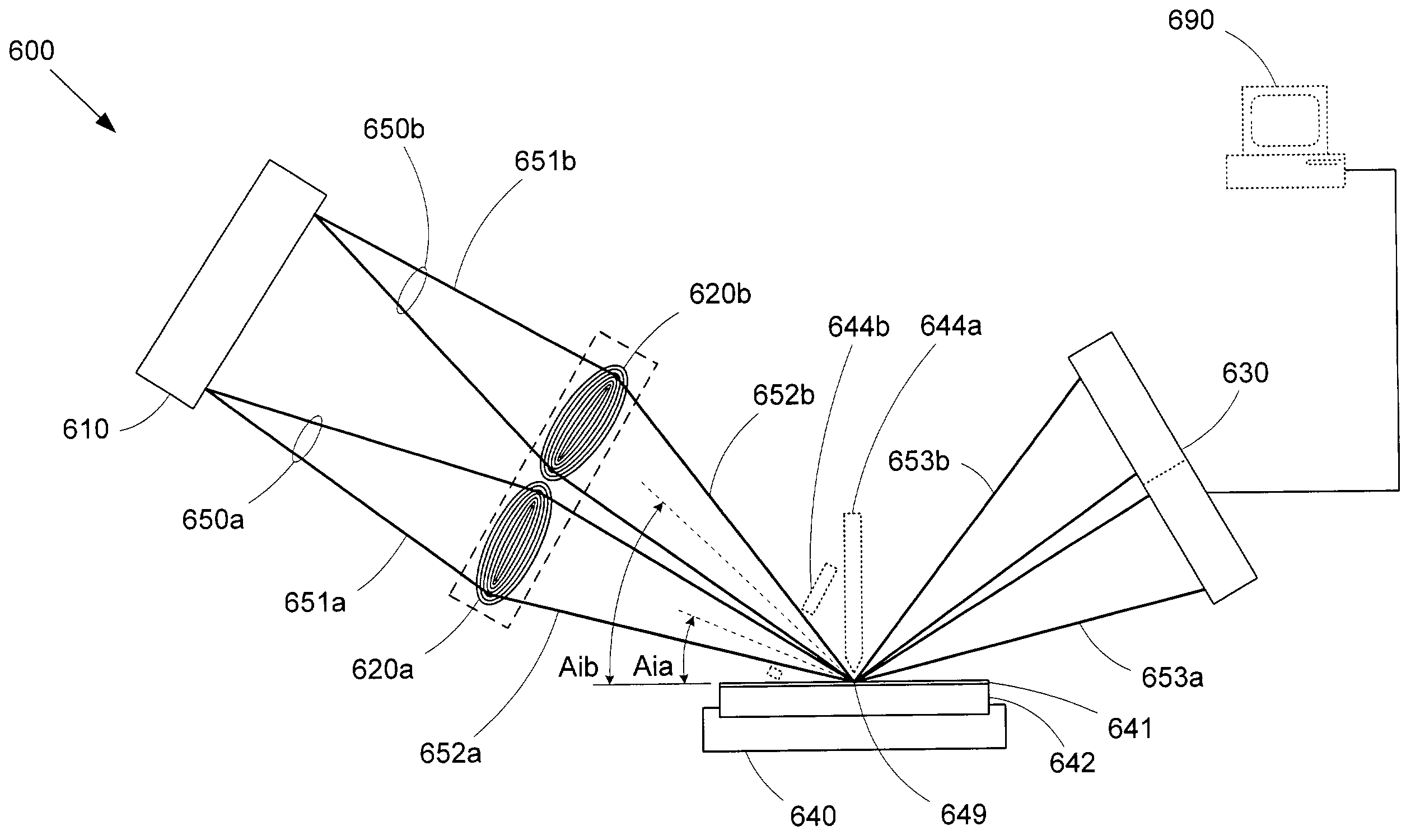
[0027]FIG. 3a shows an x-ray metrology system 300a in accordance with an embodiment of the invention. X-ray metrology system 300a includes an x-ray source 310, a transmissive x-ray optical element 320, a stage 340 for supporting a test sample 342, a detector 330, optional order blocking filters 344a and 344b, and an optional computer 390. Transmissive x-ray optical element 330 can comprise any x-ray beam reshaping element that operates via transmission of x-rays, such as a zone plate or compound refractive x-ray lens. As described above, a zone plate comprises a set of concentric metal rings that provide x-ray beam shaping via diffraction, with the actual beam shaping properties being determined by the size, shape, and spacing of the concentric metal rings. Note that the relatively flat geometry of a zone plate or compound refractive x-ray lens can provide substantial placement and positioning flexibility within x-ray metrology system 300a.

[0028]During a metrology operation, x-ray ...


PUM


Abstract

An x-ray metrology system includes one or more transmissive x-ray optical elements, such as zone plates or compound refractive x-ray lenses, to shape the x-ray beams used in the measurement operations. Each transmissive x-ray optical element can focus or collimate a source x-ray beam onto a test sample. Another transmissive x-ray optical element can be used to focus reflected or scattered x-rays onto a detector to enhance the resolving capabilities of the system. The compact geometry of transmissive x-ray optical element allows for more flexible placement and positioning than would be feasible with conventional curved crystal reflectors. For example, multiple x-ray beams can be focused onto a test sample using a transmissive x-ray optical element array. Robust zone plates can be efficiently produced using a damascene process.

Description

FIELD OF THE INVENTION[0001]This invention relates generally to metrology tools, and more particularly to a system and method for using transmissive x-ray optical elements to perform x-ray measurements.BACKGROUND OF THE INVENTION[0002]X-ray metrology systems are often used to measure and characterize small and / or hidden features in various materials. For example, thin film thickness measurement systems often use a technique known as x-ray reflectometry (XRR), which measures the interference patterns created by reflection of x-rays off a thin film. FIG. 1a shows a conventional x-ray reflectometry system 100, as described in U.S. Pat. No. 5,619,548, issued Apr. 8, 1997 to Koppel. X-ray reflectometry system 100 comprises a microfocus x-ray tube 110, an x-ray reflector 120, a detector 130, and a stage 140. A test sample 142 having a thin film layer 141 is held in place by stage 140 for the measurement process.[0003]To measure the thickness of thin film layer 141, microfocus x-ray tube 1...

Claims


Application Information

Patent Timeline
04 Jul 2006
Publication
US7072442B1
IPC
G21K1/06
CPC
G21K1/06
Inventors
JANIK, GARY R.