Combustion type power tool having motor suspension arrangement

a technology of motor suspension and combustion type, which is applied in the direction of stapling tools, nailing tools, machines/engines, etc., can solve the problems of increasing production costs, buffer functions cannot be evenly provided over an entire region of suspension members, and baking processes increase production costs, so as to increase production costs, reduce reliability of connection, and increase production costs

Inactive Publication Date: 2006-07-11
KOKI HLDG CO LTD
View PDF4 Cites 12 Cited by
  • Summary
  • Abstract
  • Description
  • Claims
  • Application Information

AI Technical Summary

Benefits of technology

[0010]However, the present inventors recognized the following disadvantages in the conventional suspension arrangement. That is, in order to fix the motor 118 to the suspension member 113, the annular grooves must be formed at the motor case 118a. In other words, an ordinary available motor cannot be employed, but a motor having a special specification must be required as the motor 118, which increases a production cost. Further, since the suspension member 113 is made from two different materials, i.e., two metal rings 113a, 113c and the rubber member 113b and these members must be integrally connected by baking, reliability as to the connection may be lowered. These members may be separated from each other if the baking is insufficient. Furthermore, the baking process increases production cost.
[0012]It is therefore an object of the present invention to provide a combustion type power tool having a motor support structure having sufficient durability and capable of being produced easily at low cost.

Problems solved by technology

In other words, an ordinary available motor cannot be employed, but a motor having a special specification must be required as the motor 118, which increases a production cost.
Furthermore, the baking process increases production cost.
As a result, buffer function cannot be evenly provided over an entire region of the suspension member 113 against the shock imparted to the motor.

Method used


Image

  • Combustion type power tool having motor suspension arrangement
  • Combustion type power tool having motor suspension arrangement
  • Combustion type power tool having motor suspension arrangement

Examples


Embodiment Construction

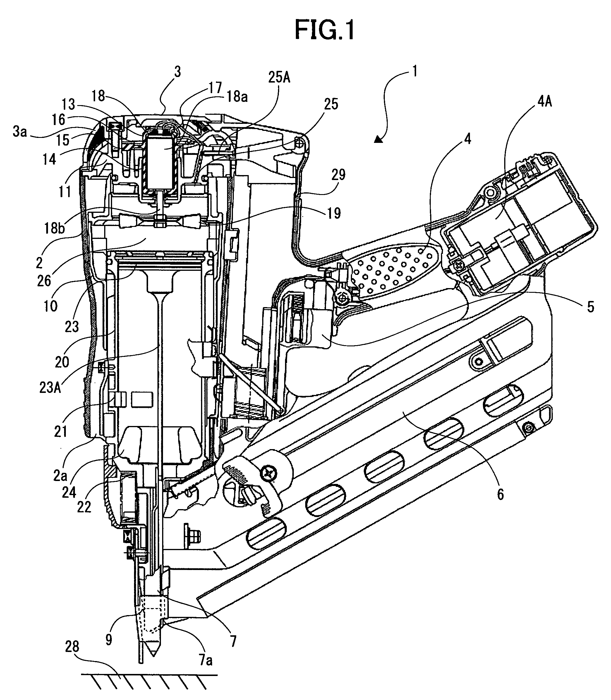
[0023]A combustion-type power tool according to an embodiment of the present invention will be described with reference to FIGS. 1 through 5. The embodiment pertains to a combustion type nail gun. The combustion type nail gun 1 has a housing 2 constituting an outer frame. A head cover 3 formed with an intake port 3a is mounted on the top of the housing 2. A handle 4 is attached to the housing 2 and extends from a side of the housing 2. The handle 4 has a trigger switch 5 and accommodates therein a battery 4A. A canister housing 29 is provided in the handle 4 at a position immediately beside the housing 2. A gas canister (not shown) containing therein a combustible gas is detachably disposed in the canister housing 29. A magazine 6 is provided at a lower side of the handle 4. The magazine 6 contains nails (not shown). The housing 2 has a lower portion formed with an exhaust port 2a for discharging a combustion gas to the atmosphere.

[0024]A nose 7 extends from a lower end of the housi...


PUM


Abstract

A combustion type power tool having a motor suspension arrangement capable of buffering a shock applied to a motor. An integral buffer member made from an elastic material is fixed to a head cap. The buffer member includes a motor storage section in which a motor casing is stored, and a plurality of buffer segments extending radially outwardly from the motor storage section and integrally therewith. Each radially outer end portion of each buffer segment is fixed to the head cap for floatingly supporting the motor storage section.

Description

BACKGROUND OF THE INVENTION[0001]The present invention relates to a combustion-type power tool, and more particularly, to such power tool having an improved motor mount structure.[0002]In a conventional combustion-type driving tool such as a nail gun, a gaseous fuel injected into a combustion chamber is ignited to cause gas expansion in the combustion chamber, which in turn causes a linear momentum of a piston. By the movement of the piston, a nail is driven into a workpiece. In order to improve combustion, a fan is disposed in the combustion chamber for agitating a combustible gas. Such conventional combustion-type driving tool is disclosed in U.S. Pat. Nos. 4,483,280, Re 32,452 and 5,197,646.[0003]A rotation drive unit such as a motor is disposed in a frame of the driving tool for rotating the fan. By the rotation of the fan, a turbulent flow is generated in the combustion chamber to promote combustion within the combustion chamber. Thus volumetric expansion occurs in the combusti...

Claims


Application Information

Patent Timeline
Patent Type & Authority Patents(United States)
IPC IPC(8): F02B71/00B25C1/08B25C1/12
CPCB25C1/08
Inventor AKIBA, YOSHITAKAFUJISAWA, HARUHISA
Owner KOKI HLDG CO LTD
Why Eureka
Try Eureka