Switching power supply controller and switching power supply

a technology of switching power supply controller and switching power supply, which is applied in the direction of power conversion systems, dc-dc conversion, instruments, etc., can solve the problems of inability to generate pwm signals with high degree of accuracy, large estimated current signals, and large circuit configurations, etc., to achieve large and complex circuit configurations, high degree of accuracy

Inactive Publication Date: 2006-07-11
TDK CORPARATION
View PDF8 Cites 20 Cited by
  • Summary
  • Abstract
  • Description
  • Claims
  • Application Information

AI Technical Summary

Benefits of technology

[0008]However, since the estimated current is generated without taking account of the influence from various loads in the circuit of the switching power supply, it includes a large DC component relative to the actual inductor current, so as to produce error between the estimated current and the real current, which results in failure in generating the PWM signal with a high degree of accuracy. In the technology described in the above patent document, therefore, a current detector is provided in order to overcome the error, the electric current flowing through the inductor is detected by this current detector, and the value of the estimated current is corrected to the value of real current twice per switching period, based on the real current detected by the current detector. Namely, the technology described in the above patent document requires the provision of the current detector for the correction of the estimated current. It also necessitates the means for detecting the current of the inductor, for executing the current mode control using the actual inductor current. For this reason, while there are demands for compact size and light weight, the switching power supply needs to have the current detecting means in the current mode control, as compared with the voltage mode control, and thus becomes larger and more complex in the circuit configuration.

Problems solved by technology

However, since the estimated current is generated without taking account of the influence from various loads in the circuit of the switching power supply, it includes a large DC component relative to the actual inductor current, so as to produce error between the estimated current and the real current, which results in failure in generating the PWM signal with a high degree of accuracy.
For this reason, while there are demands for compact size and light weight, the switching power supply needs to have the current detecting means in the current mode control, as compared with the voltage mode control, and thus becomes larger and more complex in the circuit configuration.
In passing, if the accumulated DC component should not be reset, the estimated current signal would become infinitely large, and the controller would fall into an uncontrollable state.

Method used


Image

  • Switching power supply controller and switching power supply
  • Switching power supply controller and switching power supply
  • Switching power supply controller and switching power supply

Examples


first embodiment

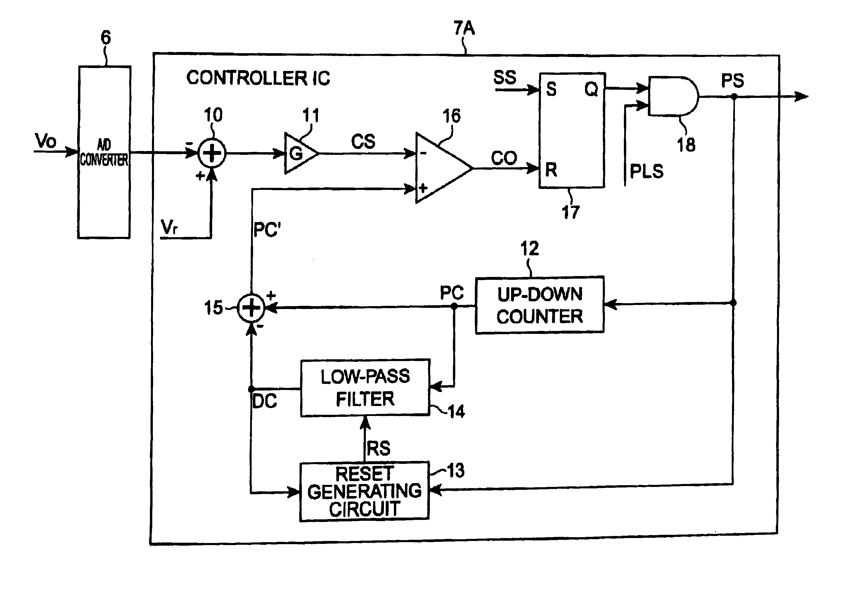
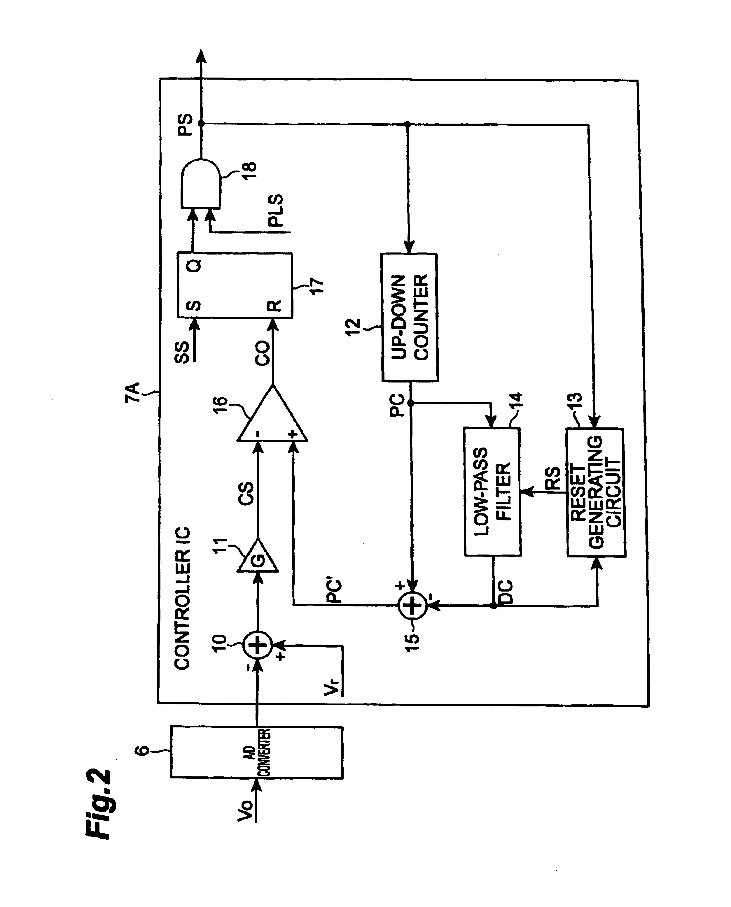
[0064]In the first embodiment, the subtractor 10 and multiplier 11 correspond to the control signal setting means as stated in the claims, the up-down counter 12 to the current estimating means in the claims, the low-pass filter 14 and subtractor 15 to the DC component removing means in the claims, the reset generating circuit 13 and low-pass filter 14 to the DC component resetting means in the claims, and the comparator 16 to the comparing means in the claims.

[0065]The subtractor 10 receives the target voltage Vr and output voltage Vo, subtracts the output voltage Vo from the target voltage Vr, and outputs the difference (Vr−Vo) to the multiplier 11.

[0066]The multiplier 11 receives the difference (Vr−Vo), multiplies the difference (Vr−Vo) by the gain G of P control, and outputs the product G(Vr−Vo) as a control signal CS to the comparator 16. This control signal CS is a target current signal in comparison with the estimated current signal PC′.

[0067]The up-down counter 12 generates ...

second embodiment

[0117]The integrator 52 is a circuit that integrates the signal after the removal of the DC component by the high-pass filter 51. By providing the integrator 52, it becomes feasible to integrate the pulse signal LS having the level values of “α” and “−β” as described above. Namely, it is feasible to integrate the pulse signal after the removal of the DC component. This can prevent the estimated current signal PC from the integrator 52 from diverging because of the influence of the DC component. Since the controller IC 7B is provided with the calculation circuit 50 comprised of the high-pass filter 51 and integrator 52 as described above, it is able to generate the estimated current signal PC, without being affected by the DC component which can be the cause of error from the real current, and thus it becomes feasible to generate the estimated current closer to the real current. Accordingly, the DC / DC converter 1 in the second embodiment does not have to be provided with the means fo...


PUM


Abstract

A controller 7A for generating a drive signal (PWM signal) PS for controlling a switching power supply, comprises control signal setting means 10, 11 for setting a control signal CS on the basis of an output voltage Vo and a target voltage Vr; current estimating means 12 for estimating an inductor current on the basis of the drive signal PS and for generating an estimated current signal PC; DC component removing means 14, 15 for extracting a DC component DC included in the estimated current signal PC and for removing the DC component DC from the estimated current signal PC; DC component resetting means 13, 14 for resetting the extracted DC component DC every predetermined time; and comparing means 16 for comparing the control signal CS with the estimated current signal PC′ after the removal of the DC component DC.

Description

BACKGROUND OF THE INVENTION[0001]1. Field of the Invention[0002]The present invention relates to a switching power supply controller and a switching power supply.[0003]2. Related Background Art[0004]A switching power supply has such properties as small size, light weight, and high efficiency and is commonly used as a power supply for microcomputers as incorporated in various devices, personal computers, and so on. These personal computers and others are progressively advancing toward lower voltage and higher processing speed, while increasing the consumption current more and more. In the switching power supply, therefore, the load current suddenly increases or decreases according to the processing load in the personal computers and others. The switching power supply possesses the property of capability of readily adapting to a wide input voltage range and is also utilized as a power supply applicable in several countries in the world or as a power supply with a wide specification se...

Claims


Application Information

Patent Timeline
Patent Type & Authority Patents(United States)
IPC IPC(8): G05F1/40H02M3/157
CPCH02M3/157H02M2001/0009H02M1/0009
Inventor UEMATSU, TAKESHIKAWASAKI, HIROSHIIMAI, TAKAKAZUMIURA, KOICHIROMATSUURA, KEN
Owner TDK CORPARATION
Why Eureka
Try Eureka