Inspection carriage for turbine blades

a turbine blade and inspection carriage technology, applied in the direction of vibration measurement in solids, instruments, material magnetic variables, etc., can solve the problems of difficult inspection of these regions, inability to detect contact stresses and cracks in these regions, and undesirable for individuals to remain in this region for extended periods

Active Publication Date: 2006-07-11
SIEMENS ENERGY INC
View PDF37 Cites 25 Cited by
  • Summary
  • Abstract
  • Description
  • Claims
  • Application Information

AI Technical Summary

Benefits of technology

[0014]The rotation axis provides the ability to rotate the inspection probe 180 degrees. This permits the probe to scan the opposing faces of adjoining blades. A limit switch limits the rotation of the inspection probe to 180 degrees to prevent damage to the connection between the probe and its associated electronics.
[0015]The paddle to which the probe is attached is inserted and retracted by remote control, thereby limiting the need to enter the hot environment of the turbine to setup and removal of the carriage. A pair of miniature video cameras is provided so that the inspector can “fly” the paddle into the Z-shroud or snubber region. A first camera, located at the top of the probe head assembly, monitors the degree to which the probe has been inserted into the inspection region. The second camera is mounted behind the paddle, looking forward from this position, so that the position of the paddle relative to the region to be inspected may be monitored. At least one camera is equipped with a light. A pair of monitors permits the inspector to monitor both cameras simultaneously.
[0018]Accordingly, it is an object of the present invention to provide an inspection apparatus having an inspection probe capable of fitting within a narrow gap between adjacent components.
[0019]It is another object of the invention to provide a non-destructive inspection apparatus capable of inspecting different regions of a turbine blade with minor reconfiguration of the components.
[0022]It is a further object of the invention to provide an inspection carriage capable of precisely moving the inspection probe along a radial axis, skew axis, axial axis and rotational axis.
[0028]It is another object of the invention to provide a non-destructive inspection apparatus that will permit faster, more efficient, and higher quality inspections of high wear portions of turbine blades.

Problems solved by technology

The blades make contact in these regions when a turbine is operating, due to bending and twisting of the blades, resulting in the potential for contact stresses and cracking within these regions.
Additionally, the narrow gap between adjacent blades in these regions makes inspection of these regions difficult while the blades are within the turbine.
Although present turbine designs provide access to the region within the turbine behind the L-0 blade, the heat within a turbine makes it undesirable for individuals to remain in this region for extended periods of time even considering that the turbine will be off when entered.

Method used


Image

  • Inspection carriage for turbine blades
  • Inspection carriage for turbine blades
  • Inspection carriage for turbine blades

Examples


Embodiment Construction

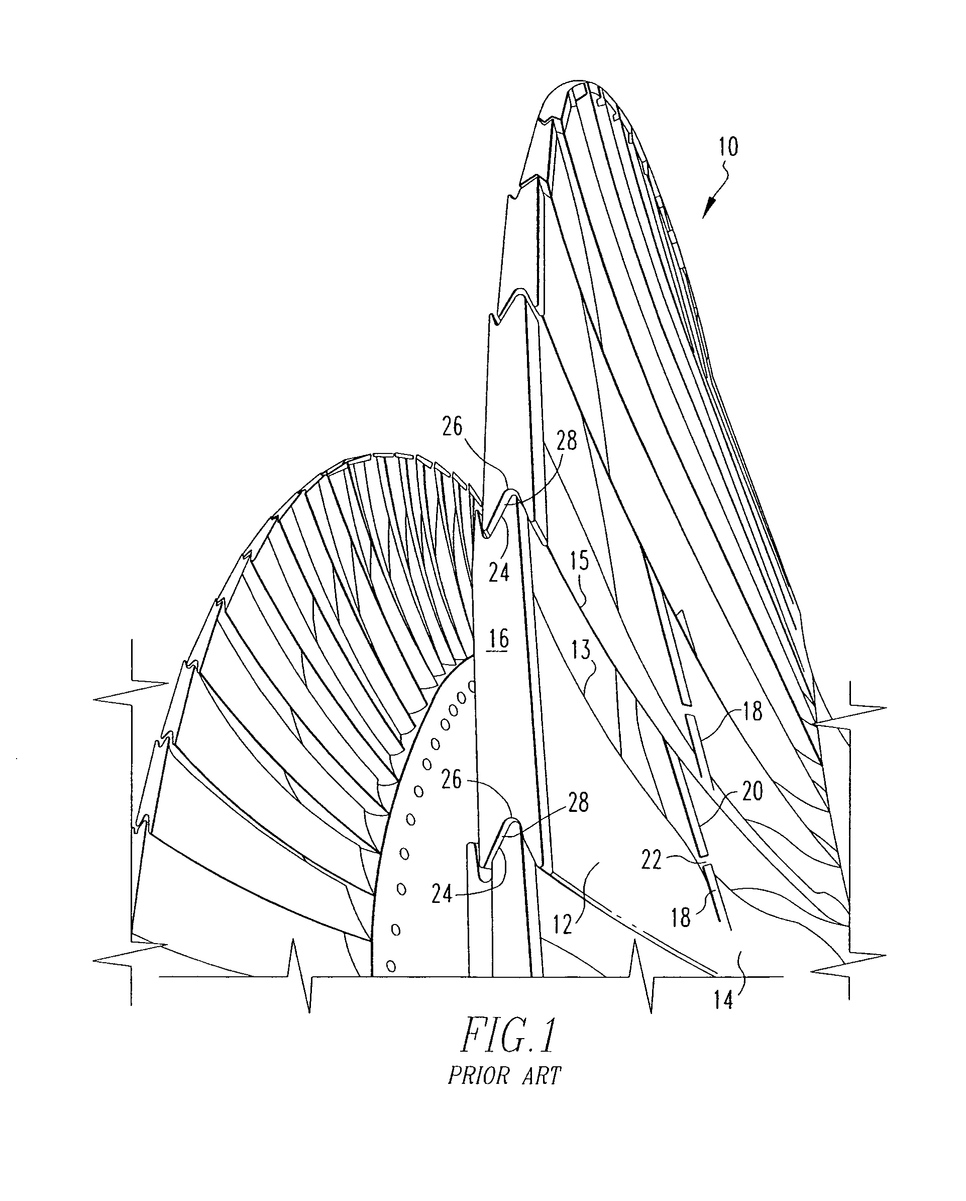
[0038]The present invention provides an inspection carriage for remotely inspecting the Z-shroud and snubber regions of turbine blades while the turbine blades remain within the turbine. Referring to FIG. 1, the L-0 row of turbine blades 10 includes individual blades 12, with each blade having a leading edge 13, trailing edge 15, center section 14 and an outside edge 16. The center section 14 of each blade 12 includes an upper cylindrical standoff 18 and a lower cylindrical standoff 20. The upper and lower standoff cylindrical standoff 18, 20 of adjacent blades 12 define a snubber region 22 therebetween. Likewise, the edge 16 includes an upper end 24 and a lower end 26. The upper and lower ends 24, 26 of adjacent blades 12 define a Z-shroud region therebetween. When the turbine is in use, the adjacent upper and lower standoff cylinders 18, 20, and adjacent upper and lower ends 24, 26 of adjacent edges 16, may rub against each other as the blades bend and twist. This contact can resu...


PUM

PropertyMeasurementUnit
of rotationaaaaaaaaaa
rotationaaaaaaaaaa
skew angleaaaaaaaaaa

Abstract

An inspection carriage provides for remote inspection of the Z-shroud and snubber regions of the blades of a steam turbine, while the blades remain in the turbine. The carriage includes a non-destructive inspection probe such as a meandering wave magnetometer probe or eddy current probe mounted on a slider, so that the probe may be moved along a radial axis, skew axis, axial axis, and rotation axis. Cameras are provided on the carriage so that the probe may be remotely guided into the region to be inspected.

Description

BACKGROUND OF THE INVENTION[0001]1. Field of the Invention[0002]The present invention relates to non-destructive inspection of steam turbines. More specifically, the invention provides an apparatus for performing non-destructive inspection of steam turbine blades while the blades remain within the turbine.[0003]2. Description of the Related Art[0004]Steam turbines typically include a plurality of rows rotating blades, with each successive row having a slightly larger diameter than the preceding row. The individual blades within each row define end regions in close proximity to the end regions of the adjacent blades, having a Z-shaped gap in between. These end regions are typically referred to as the Z-shroud region. The last, largest diameter blades in the turbine, known as the L-0 blades, also include cylindrical stand-offs at the midpoints of the blades,.defining a narrow gap between the cylindrical standoffs of adjacent blades. The gap between adjacent blades at the Z-shroud and ...

Claims


Application Information

Patent Timeline
Patent Type & Authority Patents(United States)
IPC IPC(8): G01N27/90G01R33/12
CPCG01N27/82
Inventor MOORE, CHARLES C.
Owner SIEMENS ENERGY INC
Why Eureka
Try Eureka