Optical inspection system

an optical inspection and optical technology, applied in the field of automatic optical inspection systems, can solve the problems of affecting the inspection time of the inspection board, one lighting mode is unable to properly illuminate all four sets of toe fillets, so as to achieve the effect of minimizing the inspection tim

Inactive Publication Date: 2006-07-11
LANDREX TECH CO LTD
View PDF11 Cites 52 Cited by
  • Summary
  • Abstract
  • Description
  • Claims
  • Application Information

AI Technical Summary

Benefits of technology

[0021]In operation, the circuit board is divided into stripes and each stripe is further divided into one or more fields of view (FOV). The main computer can generate a view table for determining the locations within the stripes to be imaged, by which cameras, and in which lighting modes. The head assembly moves back and forth across the stripes at a constant velocity. The cameras image points on the board in multiple, desired lighting modes in a single pass. In one embodiment, each camera can image a given point on the circuit board twice with each image having a different lighting mode. The speed of the assembly can be selected to allow the board to be imaged with a predetermin

Problems solved by technology

Thus, components on the PCB do not appear in consistent positions in fields of camera view.
One lighting mode is thus unable to properly illuminate all four sets of toe fillets.
Each pass over the board requires a significant amount of time.
Since inspection systems are often a production process bottleneck, each additional pass is thus significant.
Each pass can take several seconds and thus in many automated assembly lines, the inspection machine is the slowest machine, and is therefore a process bottleneck.
A further disadvantage of known systems is the likelihood of losing image data due to the way the image data is captured and stored.
The overhead required of the processor to manage t

Method used


Image

  • Optical inspection system
  • Optical inspection system
  • Optical inspection system

Examples


Embodiment Construction

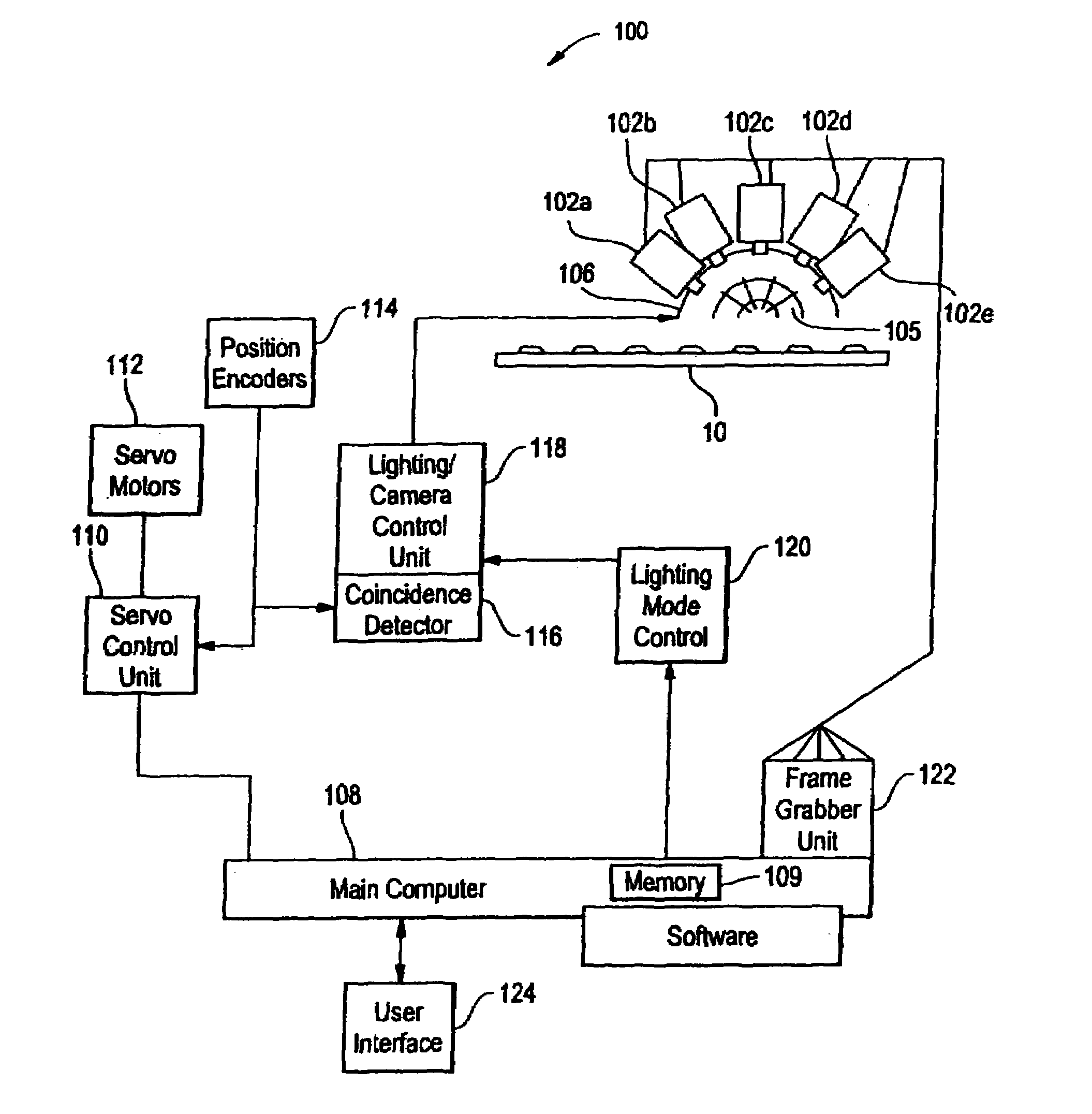
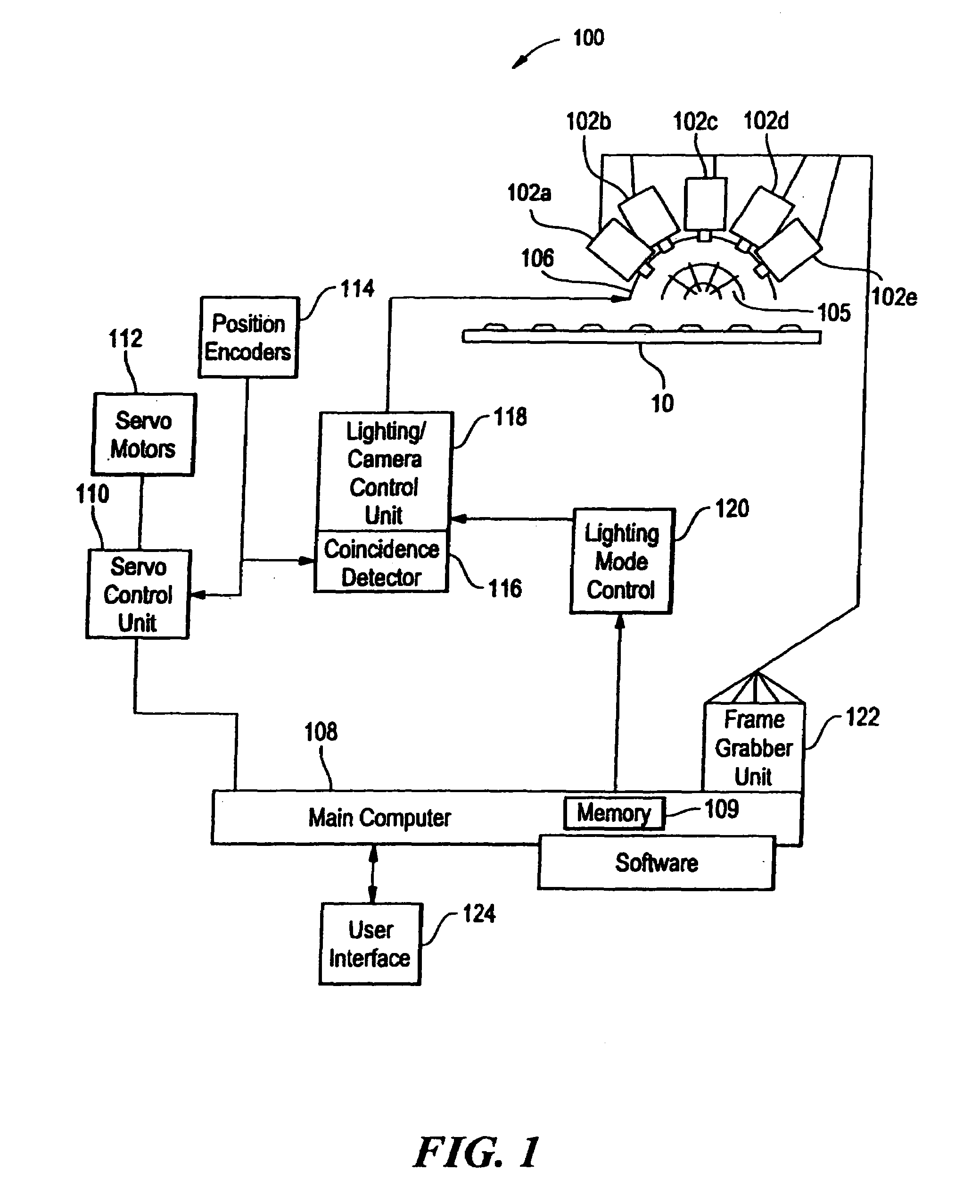
[0031]FIG. 1 shows an exemplary embodiment of an automated optical inspection (AOI) system 100 in accordance with the present invention. In general, the system 100 utilizes a series of cameras 102a–e to optically inspect an object, such as a printed circuit board (PCB) 10.

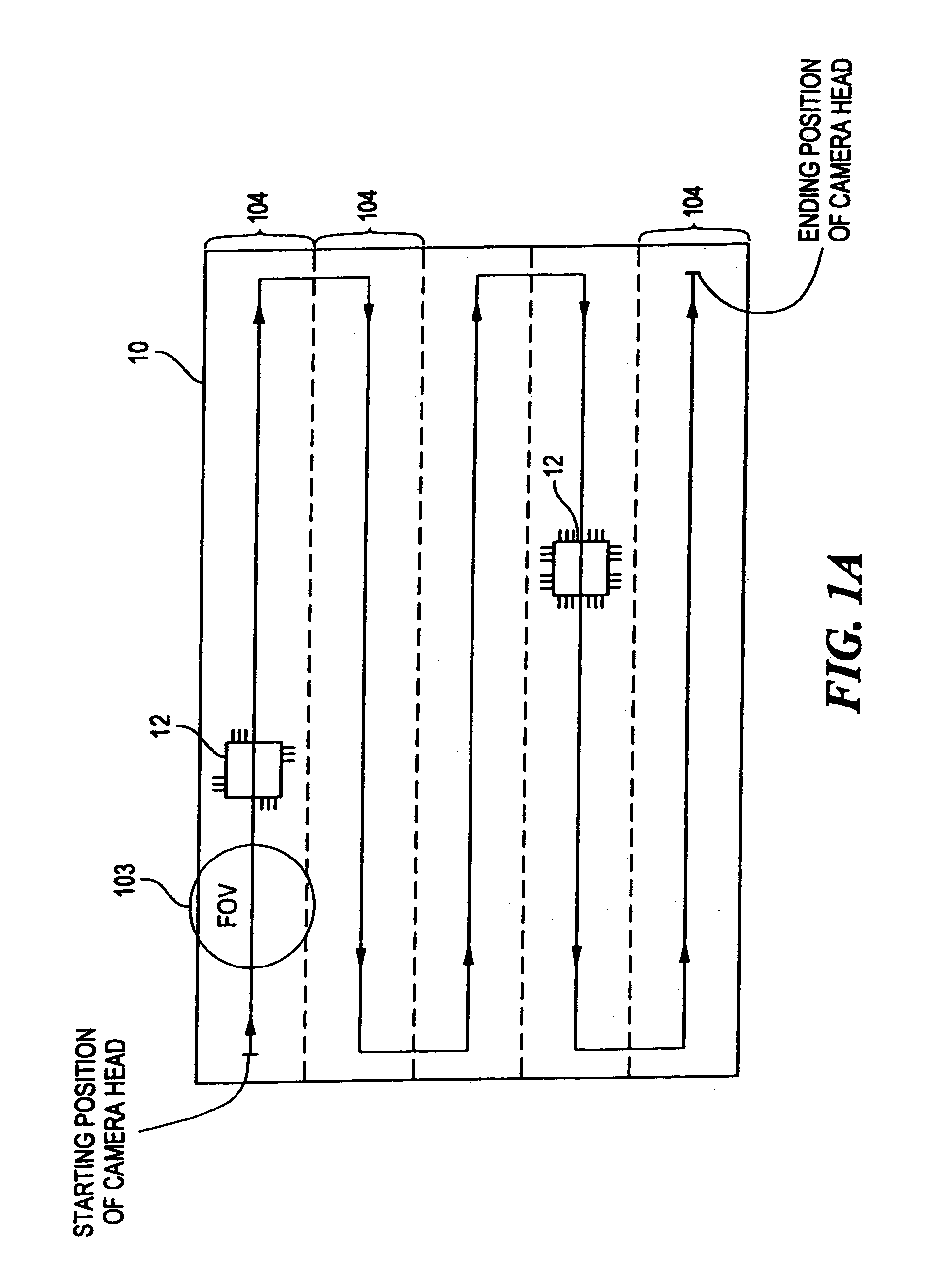
[0032]Referring briefly to FIG. 1A, the system 100 divides the PCB 10 into so-called stripes 104, which are subdivided into fields of view (FOVs) 103 that are analyzed to identify manufacturing defects associated with populating the PCB with circuit components 12, such as non-conforming solder joints. As known to one of ordinary skill in the art, the cameras move along the stripes to acquire the desired image data for the PCB. At any given time, each camera will have a predetermined FOV 103 corresponding to the position of the camera with respect to the PCB, as described more fully below. Since the inspection stations can be a bottleneck in a production environment, the decrease in board inspection time as compared...


PUM


Abstract

An automated optical inspection system includes a plurality of asynchronously triggerable cameras for providing image data of an object, such as a printed circuit board. The circuit board is divided into fields of view that are to be imaged in one or more cameras in one or more lighting modes. Each location on the board can be imaged by each camera in a plurality of lighting modes in a single pass across the board. The image data for each of the cameras can be concurrently transferred directly to main memory for opportunistic analysis by the main computer. The system allows the full bandwidth of the cameras to be utilized for reducing the inspection time of the board.

Description

CROSS REFERENCE TO RELATED APPLICATIONS[0001]Not Applicable.STATEMENT REGARDING FEDERALLY SPONSORED RESEARCH[0002]Not Applicable.FIELD OF THE INVENTION[0003]The present invention relates generally to inspection systems, and more particularly, to automated optical inspection systems.BACKGROUND OF THE INVENTION[0004]Automated optical inspection (AOI) systems are used to inspect objects, such as printed circuit boards (PCBs), for a variety of defects. The system can inspect a PCB for proper component presence and orientation, proper solder joint formation, and solder bridges. In one optical inspection application, a system can inspect the toe fillet solder joints of a quad flat pack (QFP) integrated circuit. Such a package has four edges with leads protruding from each edge. Each lead is connected to a pad on the PCB by a solder joint. An incorrectly formed solder fillet will have an appearance that can be detected using well-known image processing algorithms.[0005]Such an AOI system i...

Claims


Application Information

Patent Timeline
IPC IPC(8): H04N7/18G01N21/956G01R31/309
CPCG01N21/95684G01R31/309G01N2021/95638G01N2021/95669G01N2021/95646
Inventor RAYMOND, DOUGLAS W.FLEMING, RICHARD D.
Owner LANDREX TECH CO LTD
Why Eureka
Try Eureka