Hand-held machine tool with vibration-damped handle

a technology of hand-held machine tools and handle, which is applied in the direction of manufacturing tools, portable drilling machines, cell components, etc., can solve the problems of large stability of the handle design, suppress any tilting or tipping of the handle, and improve the guidance and stability of the handle. , the effect of high synchronization of the motions

Inactive Publication Date: 2006-07-18
ROBERT BOSCH GMBH
View PDF17 Cites 58 Cited by
  • Summary
  • Abstract
  • Description
  • Claims
  • Application Information

AI Technical Summary

Benefits of technology

[0007]A high level of synchronization of the motions transferred to the two legs of the lever can be obtained by the fact that the ends of the levers hinge-mounted on the machine housing comprise a rounding equipped with teeth, and that the hinge points of the levers are placed on the machine housing in such a way that the teeth on the ends of the levers mesh with each other. This measure largely suppresses any tilting or tipping of the handle.
[0008]The guidance and stability of the handle can be improved by the fact that two parallel levers oriented substantially at a right angle to the machine's longitudinal axis are hinge-mounted on the machine housing and on each of the two legs of the handle.
[0009]The ends of the legs of the handle preferably bear against the machine housing with spring action. A further advantageous embodiment for damping vibrations of the handle lies in the fact that one or more actuators capable of having electrical open-loop or closed-loop control are located between the handle and the machine housing, which said actuators dampen vibrations in the handle by counteracting a force or motion produced by the vibration of the machine housing.

Problems solved by technology

Additionally, the handle with the lever design has a great deal of stability.

Method used


Image

  • Hand-held machine tool with vibration-damped handle
  • Hand-held machine tool with vibration-damped handle
  • Hand-held machine tool with vibration-damped handle

Examples


Embodiment Construction

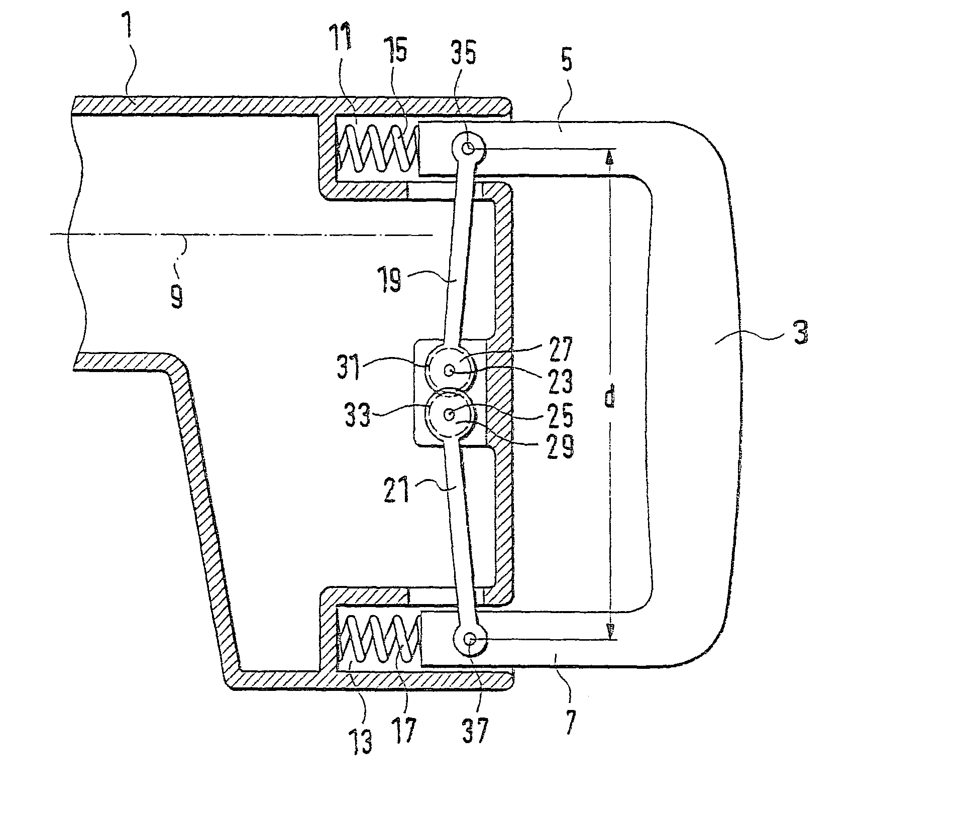
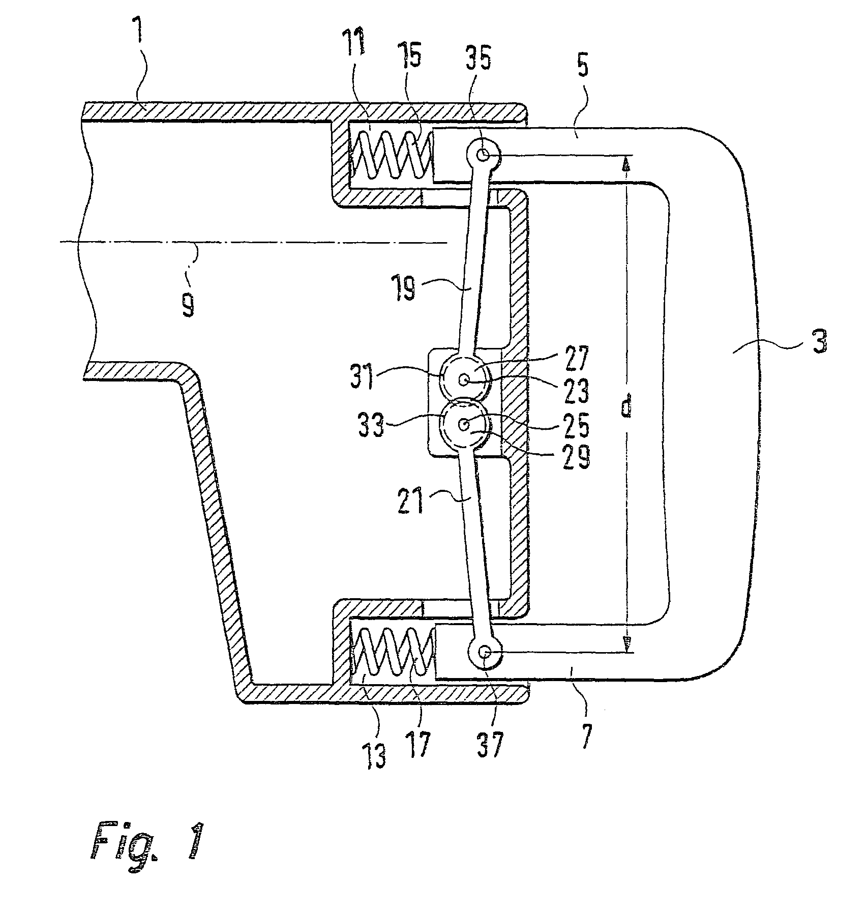
[0014]A schematic illustration of a hand power tool, e.g., a drilling hammer or a chipping hammer or the like, is shown in FIG. 1. The hand power tool is composed of a machine housing 1 in which the machine drive is located, and a handle 3 coupled with the machine housing 1. The handle 3 is designed in the shape of a “U”, and has two legs 5 and 7 that extend nearly parallel to the longitudinal axis 9 of the hand power tool.

[0015]The ends of the legs 5 and 7 of the handle 3 preferably extend into pockets 11 and 13 integrally molded on the machine housing 1. In these pockets 11 and 13, the ends of the two legs 5 and 7 bear against the machine housing 1 via spring elements 15 and 17. These spring elements 15 and 17 absorb the contact force applied by the operator to the handle 3. An advantageous embodiment for damping vibrations in the handle lies in the fact that one or more actuators capable of having electrical open-loop or closed-loop control are located between the handle 3—in add...


PUM

PropertyMeasurementUnit
angleaaaaaaaaaa
vibration-dampingaaaaaaaaaa
stabilityaaaaaaaaaa

Abstract

A very extensive decoupling of the handle from vibrations in the hand power tool is obtained by the fact that, on each of two legs (5, 7) extending nearly parallel to the longitudinal axis (9) of the hand power tool, at least one lever (19, 21) oriented substantially at a right angle to the machine's longitudinal axis (9) is hinge-mounted at one of its two ends, and by the fact that the levers (19, 21) are hinge-mounted at their other ends to a region of the machine housing (1) located between the two legs (5, 7) of the handle (3).

Description

BACKGROUND OF THE INVENTION[0001]The present invention concerns a hand power tool with vibration-damped handle that has two legs extending nearly parallel to the longitudinal axis of the hand power tool and that is coupled with the machine housing with spring action.[0002]In the case of hand power tools in particular having a striking drive, e.g., drilling hammers, chipping hammers, and the like, very strong vibrations occur in the machine that are transferred to the handle of the machine and are not only unpleasant for the operator, but they can be harmful as well. For example, measures for damping the handle of a hand power tool against vibrations are made known in DE 195 03 526 A1. These measures include, for example, coupling the handle with the machine housing at one end via a damping spring or a spring system, and interconnecting the handle with the machine housing at the opposite end by means of a pivot joint. In this publication it is also proposed that the two ends of two l...

Claims


Application Information

Patent Timeline
Patent Type & Authority Patents(United States)
IPC IPC(8): B25G1/01B25D17/24B23B45/16B25D17/04
CPCB25D17/043Y10T16/48Y10T16/476Y10T16/513
Inventor MEIXNER, GERHARD
Owner ROBERT BOSCH GMBH
Why Eureka
Try Eureka