Dual-functioning mechanism for startup during winding of web material and for splicing during unwinding

a technology of web material and splicing, which is applied in the direction of cellulosic plastic layered products, instruments, photosensitive materials, etc., can solve the problems of low adhesion bonding strength and portion of web components

Inactive Publication Date: 2006-07-18
SONOCO DEV INC
View PDF18 Cites 59 Cited by
  • Summary
  • Abstract
  • Description
  • Claims
  • Application Information

AI Technical Summary

Benefits of technology

[0008]The adhesive on the leading portion of the web component in one embodiment is substantially completely covered by the free end portion of the core component when the two components are joined together at startup of winding of the web. In this manner, the adhesive on the leading portion is prevented from sticking to a subsequent turn of the web during winding.
[0012]The core-attaching portion of the core component can have a double-sided adhesive tape, or a layer of adhesive, disposed on its lower surface for attaching the core component to the core. The core-facing side of the adhesive tape, or the adhesive layer, can have a release liner attached to it to prevent sticking of the core component to various objects until it is desired to attach the core component to the core. The release liner can be peeled off to expose the adhesive tape or adhesive layer just prior to attaching the core component to the core.

Problems solved by technology

However, the adhesive bonding strength is low enough to allow the leading portion of the web component to detach from the core component at completion of unwinding of the roll such that the adhesive on the leading portion extending from the tail end of the web is exposed for attachment to a leading end of another web being unwound from a new roll to splice the webs together.

Method used


Image

  • Dual-functioning mechanism for startup during winding of web material and for splicing during unwinding
  • Dual-functioning mechanism for startup during winding of web material and for splicing during unwinding
  • Dual-functioning mechanism for startup during winding of web material and for splicing during unwinding

Examples


first embodiment

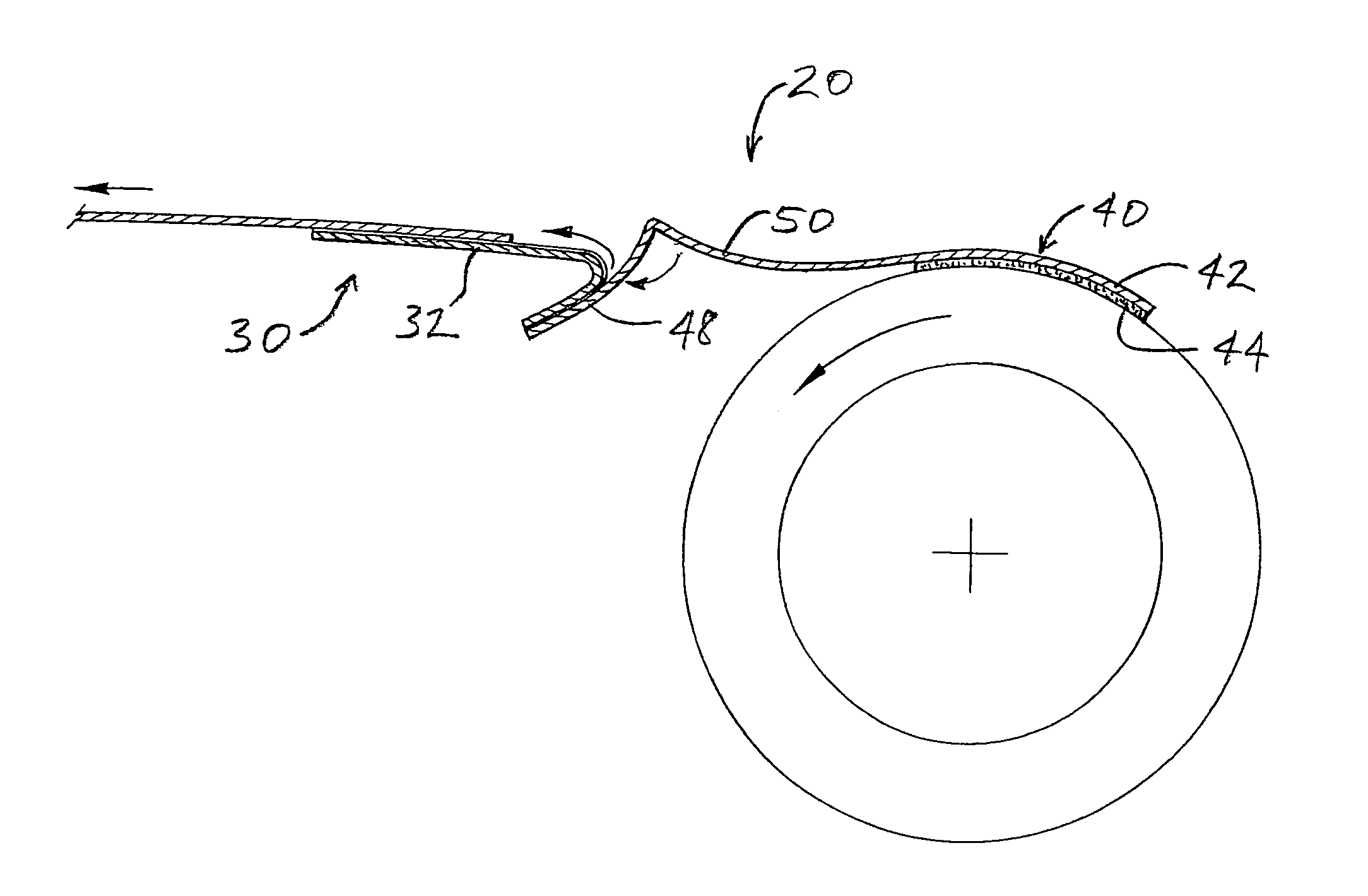
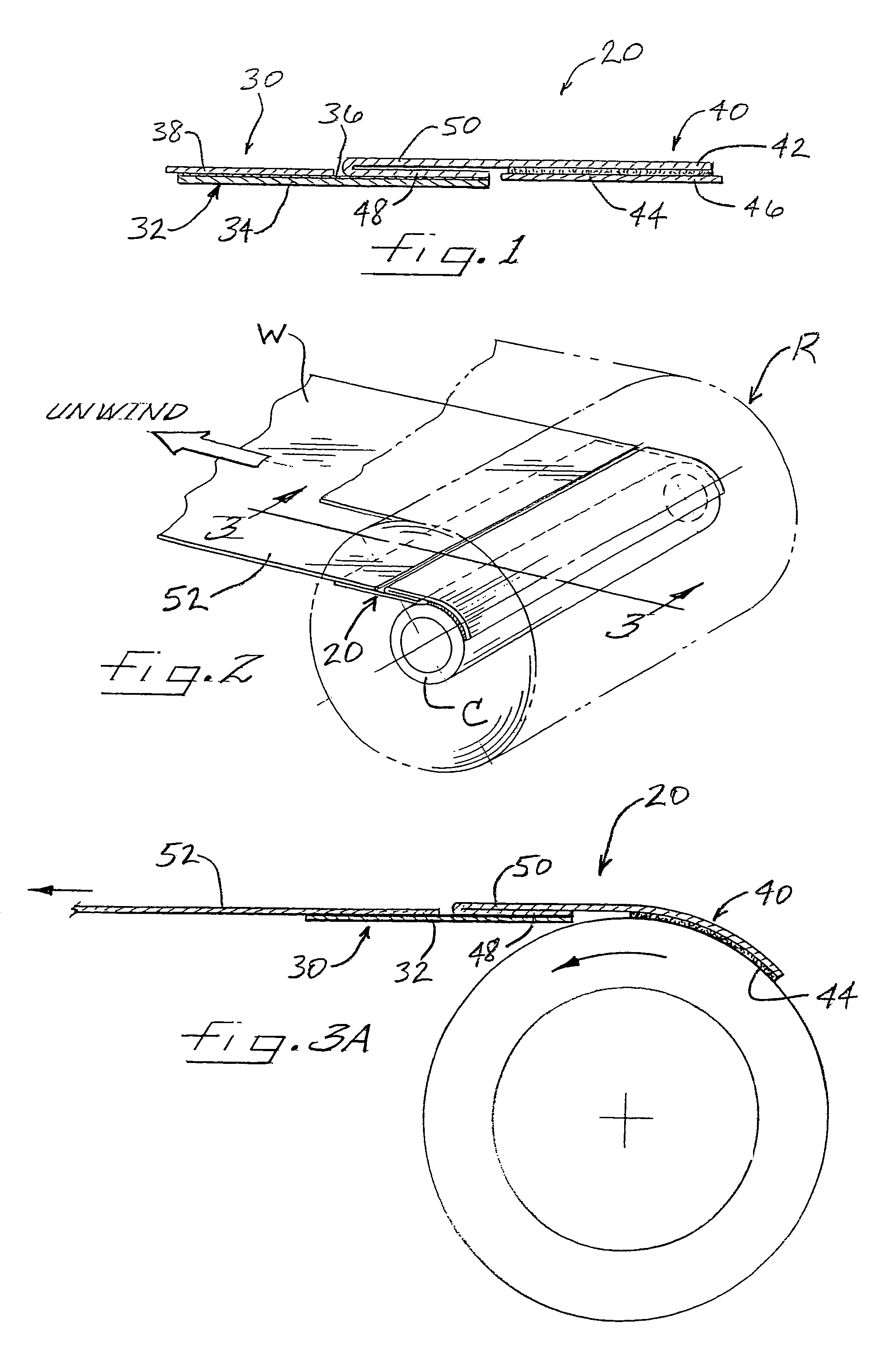
[0029]A dual-functioning mechanism for startup and splicing of a webs in accordance with the invention, is depicted in FIG. 1 and broadly designated by reference numeral 20. The mechanism 20 comprises a web component 30 for attachment to a tail end of a web and a core component 40 for attachment to a winding core. The web component comprises a splicing tape 32 formed by a backing 34 of suitable sheet material (e.g., paper, plastic film, cloth, etc.) and a layer of adhesive 36 covering one side of the backing. A release liner 38, which can comprise, for example, a silicone-coated paper or the like, covers the adhesive 36 on one lengthwise portion of the splicing tape and is adhered to the adhesive in releasable fashion. The remaining length of the splicing tape is adhered by the adhesive 36 to a portion of the core component 40. The adhesive 36 preferably comprises a pressure-sensitive adhesive (PSA), i.e., a material that adheres to a wide variety of materials upon application of pr...

fifth embodiment

[0046]a mechanism 220 in accordance with the invention is shown in FIG. 7. The mechanism 220 includes a web component 230 comprising a splicing tape 232 and a core component 240 comprising a substrate 242 having adhesive 244 on a core-attaching portion of the substrate. Both the splicing tape and the substrate are flat (i.e., not folded). A leading portion of the splicing tape 232 is releasably adhered to a free end portion of the substrate 242, and a tail portion of the splicing tape is adhered to the tail end 52 of a web. The mechanism thereby attaches the tail end to the core to assist in startup of winding of the web about the core to form a roll. At completion of unwinding of the roll, as the tail end of the web pulls the splicing tape 232 away from the core, the adhesive interface between the splicing tape and the core component 240 is initially placed in shear; the resulting shear stress may be sufficient to break the adhesive bond and detach the splicing tape from the core c...

sixth embodiment

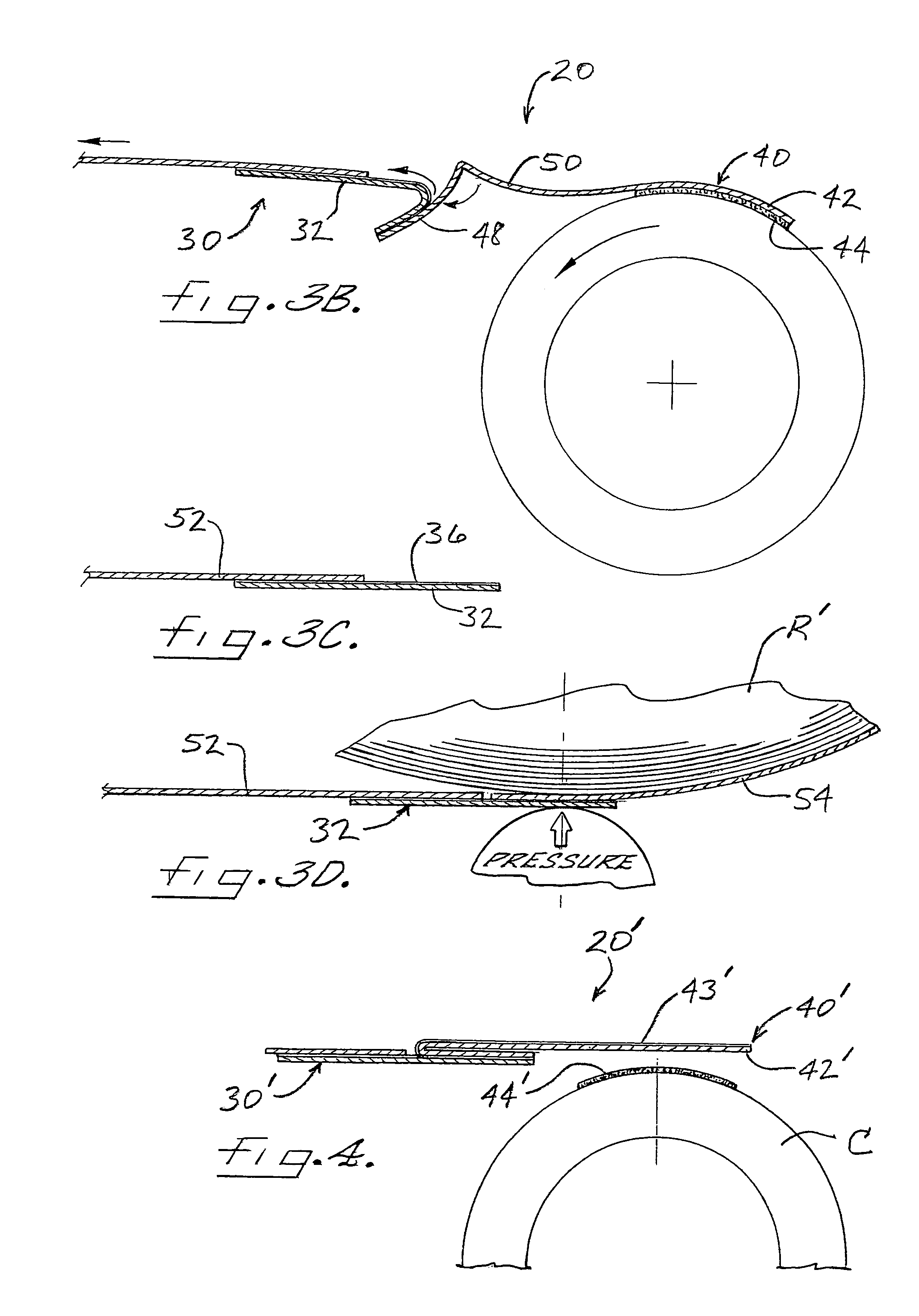
[0047]FIGS. 8A and 8B depict a mechanism 320 in accordance with the invention. The mechanism 320 includes a web component 330 comprising a folded splicing tape 332 substantially as described in connection with FIG. 6. The core component 340 comprises a layer of release material 343 disposed on the cylindrical outer surface of the winding core. The leading folded portion of the splicing tape 332 is releasably adhered to the release material 343 on the core and the tail portion of the splicing tape is adhered to the tail end 52 of a web so as to attach the tail end to the core and thereby assist in startup of winding of the web about the core. At completion of unwinding, as the tail end of the web is advanced away from the core, the splicing tape 332 is pulled away from the core and unfolds and peels off from the release material 343 of the core component. Once the splicing tape completely detaches form the core component 340, the splicing tape assumes the configuration as shown in FI...


PUM

PropertyMeasurementUnit
adhesive bonding strengthaaaaaaaaaa
lengthaaaaaaaaaa
tensionaaaaaaaaaa

Abstract

A tail end of a web is attached to a winding core via a two-component mechanism having a core component attached to the core and a web component attached to the web, the two components being attached to each other in releasable fashion. The mechanism assists startup of winding. Upon completion of unwinding, the web component detaches from the core component to expose a region of adhesive on a part of the web component that extends from the tail end of the web. The tail end thus can be spliced to a leading end of another web by attaching the leading end to the exposed adhesive on the web component.

Description

BACKGROUND OF THE INVENTION[0001]The invention relates to the winding of web materials about winding cores to form rolls of the materials, and the subsequent unwinding of the web materials from the rolls and splicing of a web tail end of a depleted roll to the web leading end of a new roll.[0002]Web materials such as polymer film, paper, nonwoven or woven textile, metal foil, sheet metal, and others, are used in the manufacture of a variety of products. The web materials generally are provided in the form of large rolls formed by winding the web material about a winding core. To begin the winding process, a tail end of a web is attached to the winding core and the core is rotated about its axis to wind the web into a roll.[0003]To manufacture products, the web material is unwound from the roll and subjected to converting operations, the particulars of which vary depending on the products being made. When the web from one roll is fully unwound, a splicing operation is performed where...

Claims


Application Information

Patent Timeline
Patent Type & Authority Patents(United States)
IPC IPC(8): B31F5/00B32B9/00B65H19/00B65H19/18B65H19/10B65H19/28
CPCB65H19/10B65H19/28Y10S428/906Y10T428/14Y10T428/24793Y10T428/24777Y10T428/1476Y10T428/149
Inventor ADAMS, ANGELA HURST
Owner SONOCO DEV INC
Why Eureka
Try Eureka