
Electrical conduit to junction box connection system

a technology of electrical conduit and junction box, which is applied in the direction of insulating bodies, insulated conductors, cables, etc., can solve the problems of not having a removable cover of junction boxes, and achieve the effect of convenient connection of electrical conduits, and convenient operation

Inactive Publication Date: 2006-07-18
RJS ELECTRICAL PROD
View PDF18 Cites 71 Cited by
  • Summary
  • Abstract
  • Description
  • Claims
  • Application Information

AI Technical Summary

Benefits of technology

[0014]The electrical conduit to junction box connection system of the instant invention is designed to be installed quickly and easily without tools, does not require access to the interior of the junction box, and does not need to be disassembled before connecting it to a junction box. Additionally, the instant invention improves safety because it provides a rigid connection, it conserves space within the enclosure, and it can be made to be liquid tight.
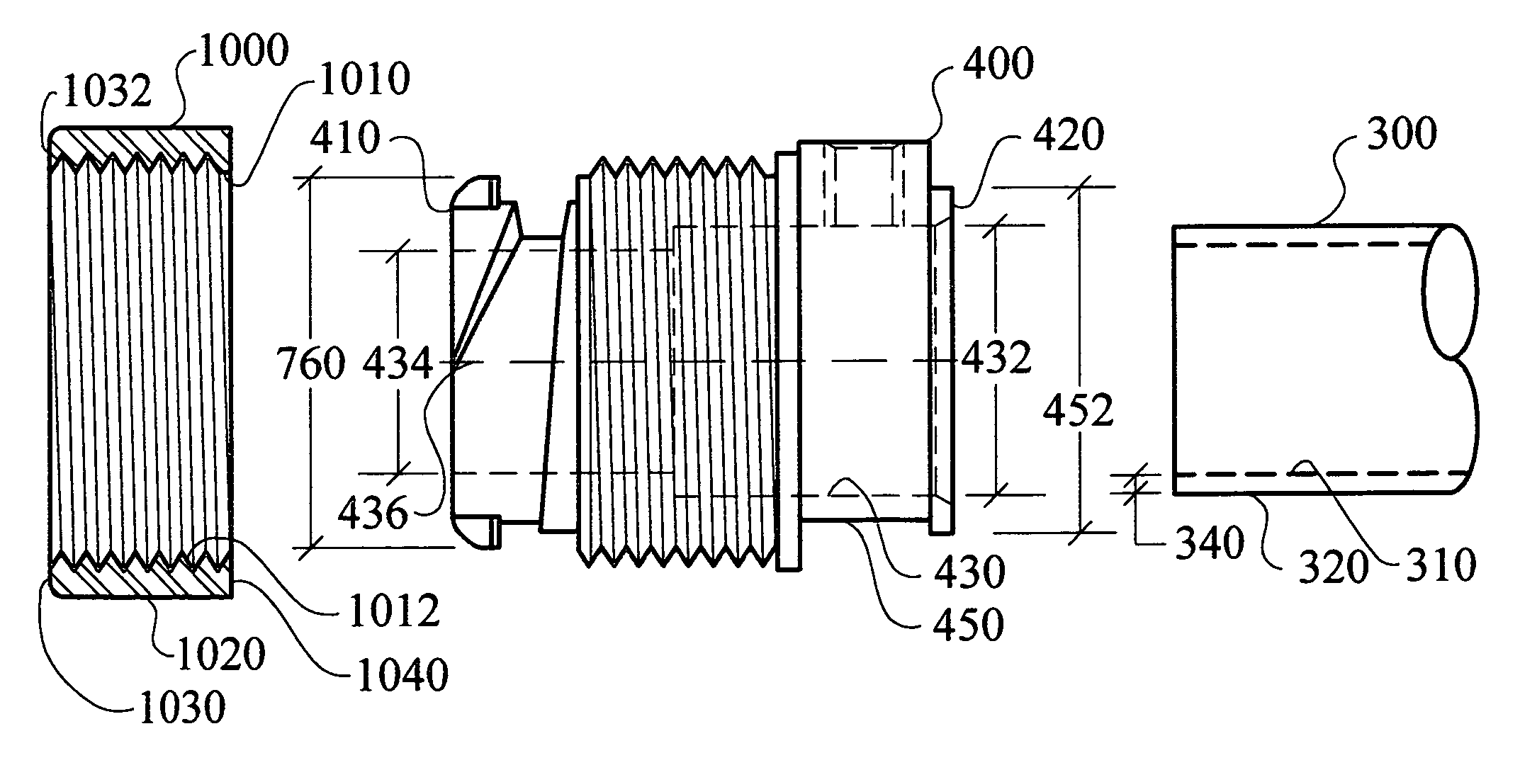
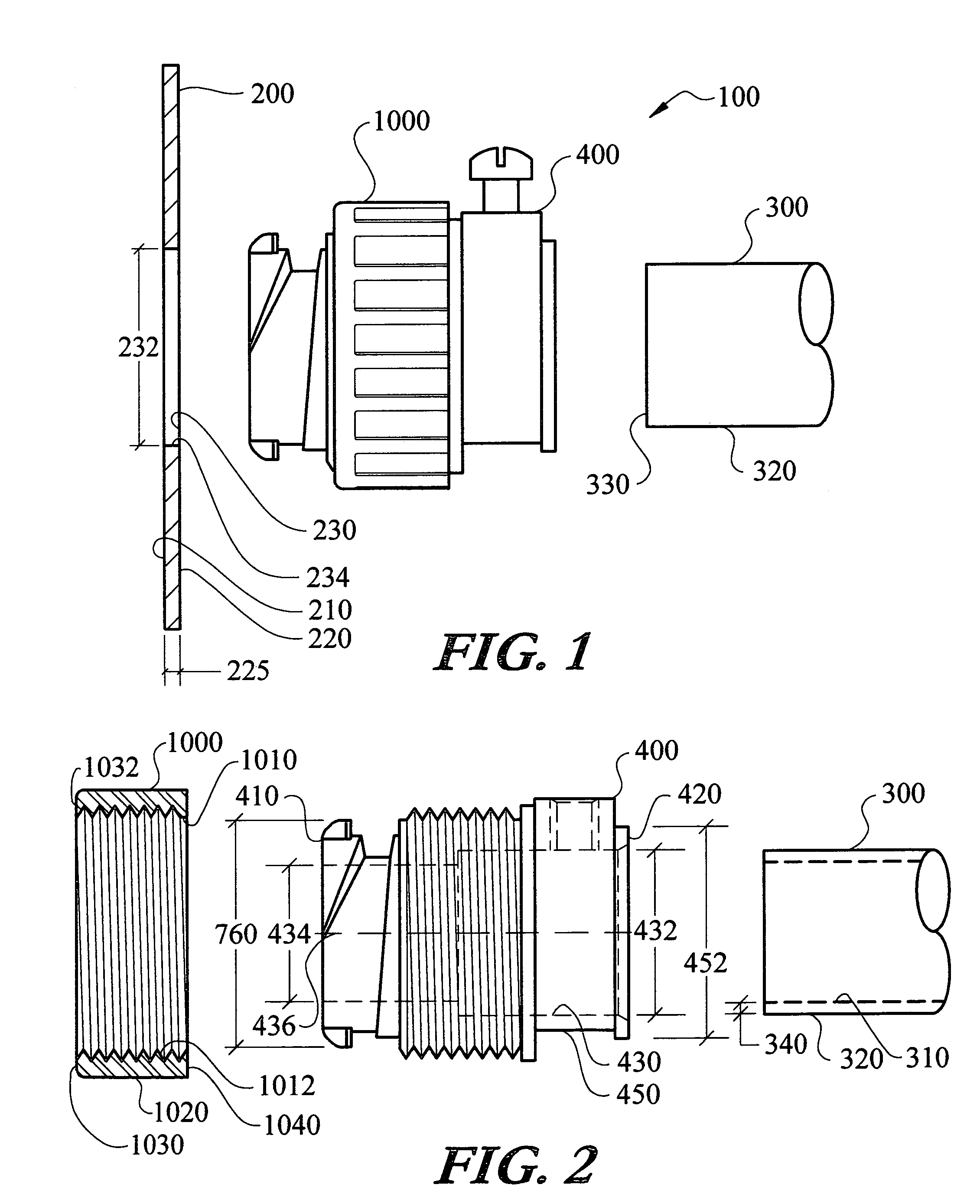
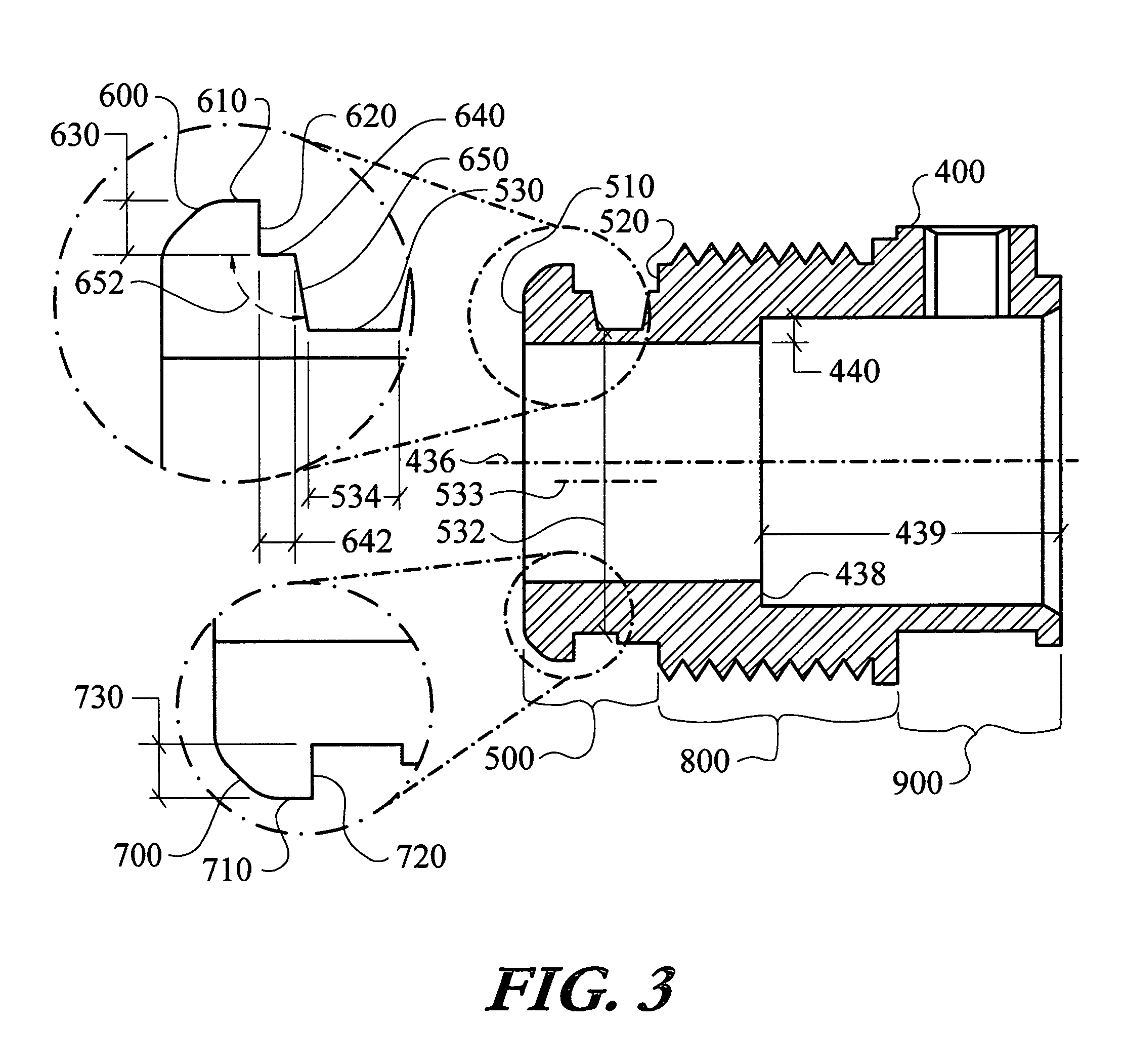
[0017]The first region is a box engagement region. The box engagement region is positioned at one end of the body and cooperates with the knockout to attach the body to the junction box. The box engagement region has a leading and a follower tab which extend radially from the box engagement region. Also, within the box engagement region is a root surface. The root surface facilitates the connection of the system to the junction box. The root surface has a root surface diameter that is not coaxial with the body inlet or the body outlet diameter. The leading tab has a perimeter edge, a centering ledge, and a centering flank. The leading tab centering flank extends from the root surface to the leading tab centering ledge. A flank angle exists between the leading tab centering flank and the leading tab centering ledge. The flank angle is between approximately ninety-one degrees and approximately one hundred and seventy-nine degrees. The follower tab also has a perimeter edge and a primary contact surface. The leading tab perimeter edge and the follower tab perimeter edge form a tab perimeter diameter. The perimeter diameter is larger than the knockout diameter.
[0019]The compression nut is another primary component of the system. The compression nut operates to rigidly fix the body to the junction box by compressing the junction box wall between the leading and follower tabs and the compression nut. The compression nut has an exterior surface which can be designed to accept tools or be shaped to allow operation by hand. In either case, operation of the compression nut is accomplished on the outside of the junction box—the electrician is not required to thrust tools or their hand inside the junction box. The compression nut will forcibly engage the exterior surface of the junction box, with or without tools, thereby providing the desired rigid, space saving, and liquid tight connection.
[0020]The design of the electrical conduit to junction box connection system facilitates the connection of the conduit to the junction box for running electrical wiring and the like to proceed quickly and easily. Consequently, users will realize substantial labor cost savings versus assembly with prior art systems. Initially, the leading tab is inserted from the outside of the box through the knockout by angling the body such that the central axis is not orthogonal to the knockout. Once the leading tab is on the inside of the junction box, the knockout edge is brought into contact with the root surface. The central axis is oriented orthogonally to the knockout while holding the knockout edge in contact with the root surface. In this manner the follower tab clears the knockout edge and passes through the knockout into the junction box. At this point both the leading and follower tabs are on the inside of the junction box. The body is drawn tight to the junction box by rotating the compression nut so that the nut contact edge presses against the box exterior surface. In one embodiment, the compression nut and nut engagement region threads are left-handed threads, that is, reverse from the normal orientation, to enhance effectiveness of the system. By continuing to rotate the compression nut, the nut contact edge forces the knockout edge onto the leading tab centering flank. Further rotation of the compression nut pushes the knockout edge onto the leading tab centering ledge, substantially centering the body into the knockout and compressing the junction box between the compression nut and the leading and follower tabs. The system is disconnected from the junction box by reversing the above operation.

Problems solved by technology

Alternatively, some junction boxes do not have removable covers for exposing prefabricated knockouts.

Method used


Image

  • Electrical conduit to junction box connection system
  • Electrical conduit to junction box connection system
  • Electrical conduit to junction box connection system

Examples


Embodiment Construction

[0042]The electrical conduit to junction box connection system (100) of the instant invention enables a significant advance in the state of the art. The preferred embodiments of the device accomplish this by new and novel arrangements of elements and methods that are configured in unique and novel ways and which demonstrate previously unavailable but preferred and desirable capabilities. The detailed description set forth below in connection with the drawings is intended merely as a description of the presently preferred embodiments of the invention, and is not intended to represent the only form in which the present invention may be constructed or utilized. The description sets forth the designs, functions, means, and methods of implementing the invention in connection with the illustrated embodiments. It is to be understood, however, that the same or equivalent functions and features may be accomplished by different embodiments that are also intended to be encompassed within the s...


PUM


Abstract

An electrical conduit to junction box connection system is designed connect conduit to junction boxes. The system incorporates a compression nut and a body. The body includes a box engagement region, a nut engagement region, and a conduit engagement region. The box engagement region includes a radially extending leading and follower tab, a root surface, a tab centering ledge, and a tab centering flank. The nut engagement region includes a nut engagement region thread that cooperates with the compression nut. The conduit engagement region includes a conduit compression system. During installation, the leading tab is inserted into the knockout. An edge of the knockout is positioned in contact with the root surface. The body is reoriented which positions the follower tab inside the junction box. The compression nut is manipulated to compress the junction box between the compression nut and the leading and follower tabs.

Description

TECHNICAL FIELD[0001]The instant invention relates to adapters for connecting electrical conduit to junction boxes, outlet boxes, or other enclosures, and, more particularly, to an electrical conduit connector with a compression nut and a body, that together provide a system for connecting a conduit to a junction box in a quick, safe, and rigid fashion.BACKGROUND OF THE INVENTION[0002]The most common use for electrical conduit connectors is to facilitate the connection of a conduit or cable to a junction box. The junction box can be a variety of electrical enclosures such as an outlet box, transformer enclosure, circuit panel, lighting fixture—the list is nearly endless. Similarly, the conduit can be rigid or flexible, or could be hose, other tubing capable of routing electrical wire, or cable. Cable can be non-metallic sheathed cable, portable cord, or a variety of other types of electrical conductors. The instant invention is equally successful in connecting a plurality of types o...

Claims


Application Information

Patent Timeline
Patent Type & Authority Patents(United States)
IPC IPC(8): H02G3/06
CPCH02G3/0616
Inventor SHEEHAN, ROBERT K.
Owner RJS ELECTRICAL PROD
Learn More