
Ion beam scanning control methods and systems for ion implantation uniformity

a control method and beam technology, applied in the field of ion implantation systems, can solve the problems of less suitable techniques, workpiece dose produced by the beam some distance from the beam center, and difficulty in maintaining the convergence of the ion beam, so as to reduce the deviation of the current density profile

Active Publication Date: 2006-07-18
AXCELIS TECHNOLOGIES
View PDF5 Cites 5 Cited by
  • Summary
  • Abstract
  • Description
  • Claims
  • Application Information

AI Technical Summary

Benefits of technology

The present invention relates to systems and methods for calibrating an ion beam scanner in an ion implantation system. The invention provides compensation for implant contributions produced by the beam some distance from the beam center, and is thus particularly suitable for use in low energy ion implanters having relatively wide beams and / or in situations where the lateral beam width varies along the scan direction to provide uniform implantation across a workpiece surface. The invention may also be employed to reduce excess overscan, thereby improving system scan efficiency without sacrificing implant uniformity. The technical effect of the invention is to improve the accuracy and precision of ion implantation systems.

Problems solved by technology

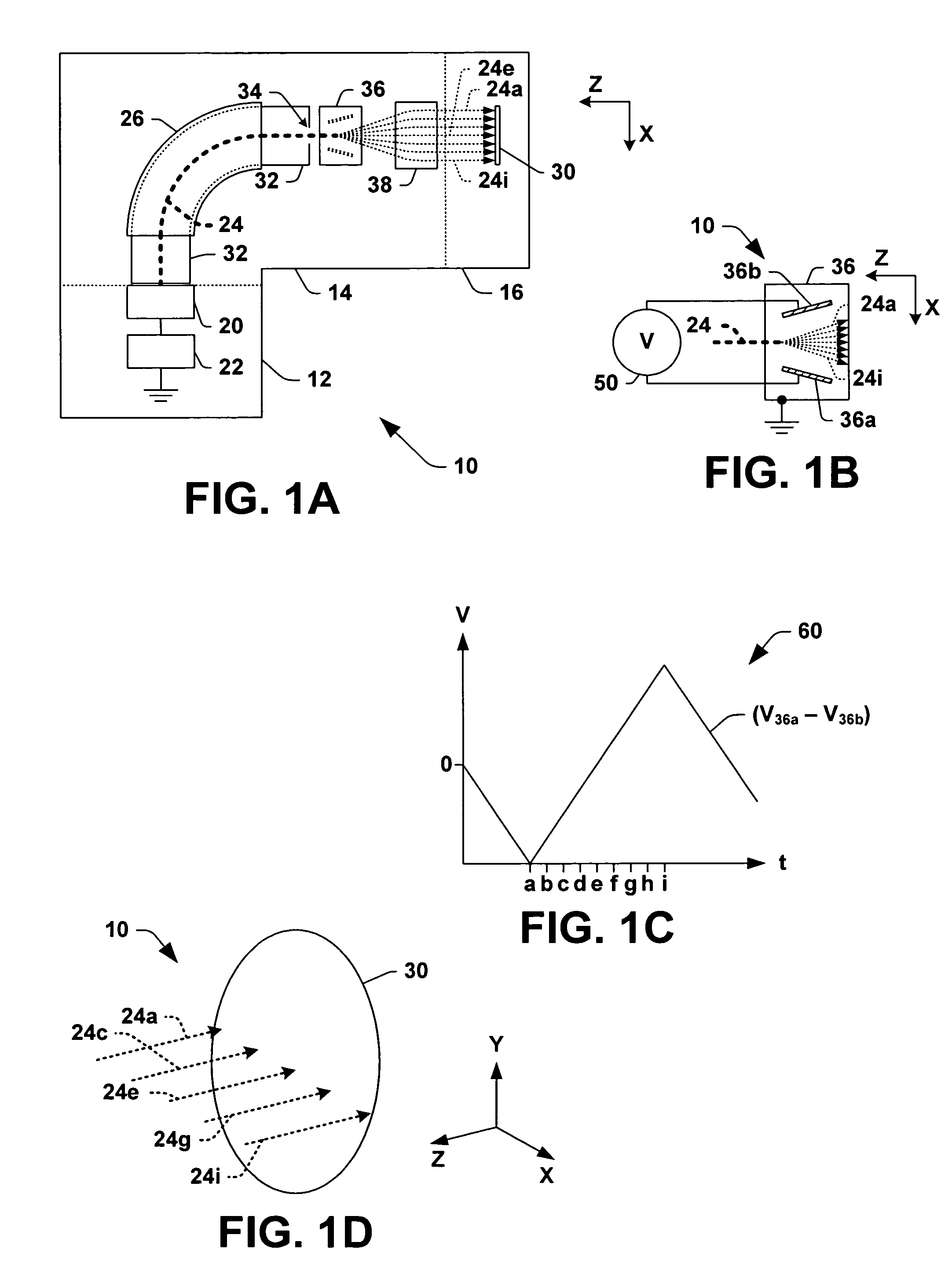
Conversely, high current, low energy ion beams 24 are typically employed for high dose, shallow depth ion implantation, in which case the lower energy of the ions commonly causes difficulties in maintaining convergence of the ion beam 24.
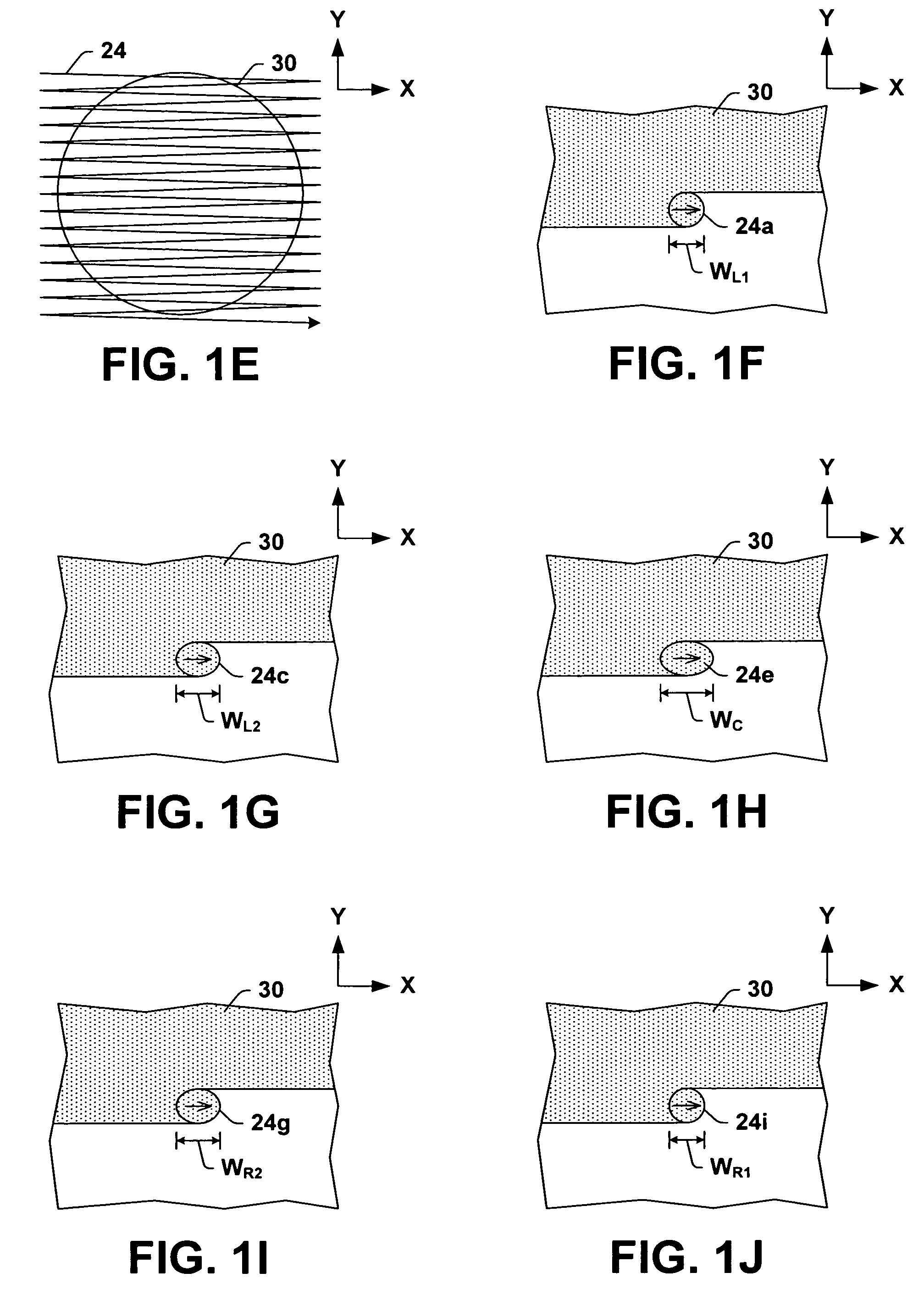
Although the conventional point-to-point scanner calibration techniques may be adequate where the width of the ion beam 24 is narrow and the beam width is relatively constant across the target area, these techniques are less suitable in the case of wider beams 24 and / or in situations where the beam width varies along the scan direction, as in the example of FIGS. 1F–1J.
In particular, if the beam 24 is wide and / or variable across the target area, the point-to-point technique fails to account for the workpiece dose produced by the beam some distance from the beam center.
This situation is particularly problematic with low energy ion beams 24 that experience space charge expansion (e.g., lateral divergence in the scan or X direction).
However, the time that the scanned beam 24 spends outside the target area is essentially wasted, and detracts from the system scan efficiency, defined as the time spent on the target workpiece 30 divided by the total scan time.

Method used


Image

  • Ion beam scanning control methods and systems for ion implantation uniformity
  • Ion beam scanning control methods and systems for ion implantation uniformity
  • Ion beam scanning control methods and systems for ion implantation uniformity

Examples


Embodiment Construction

[0043]The present invention will now be described with reference to the drawings wherein like reference numerals are used to refer to like elements throughout, and wherein the illustrated structures are not necessarily drawn to scale. The invention provides methods and systems for calibrating an ion beam scanner in an ion implantation system, which may be employed to improve implant uniformity and to improve system scan efficiency by reducing excess overscan.

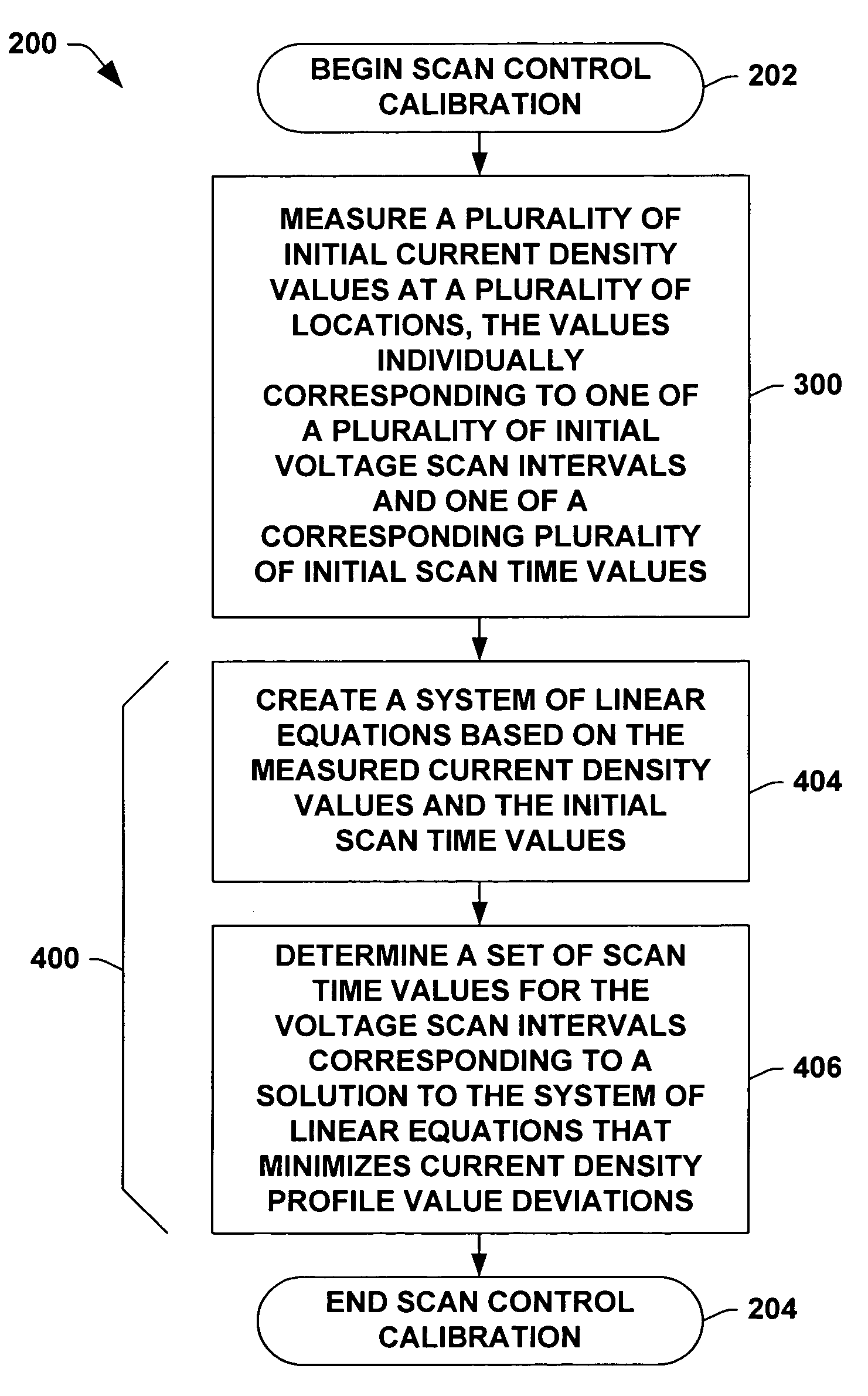
[0044]FIG. 2 illustrates an exemplary beam scanner calibration method 200 in accordance with one or more aspects of the present invention, in which measurements are taken and computations are performed to determine a set of scan times for constructing a piecewise linear scanner voltage waveform to improve implant uniformity and to reduce excess overscan in an ion implantation system. FIGS. 3A and 5 illustrate exemplary measurement and computation sequences, respectively, that may be employed in the method 200, as described furth...


PUM


Abstract

Methods are provided for calibrating an ion beam scanner in an ion implantation system, comprising measuring a plurality of initial current density values at a plurality of locations along a scan direction, where the values individually correspond to one of a plurality of initial voltage scan intervals and one of a corresponding plurality of initial scan time values, creating a system of linear equations based on the measured initial current density values and the initial voltage scan intervals, and determining a set of scan time values that correspond to a solution to the system of linear equations that reduces current density profile deviations. A calibration system is provided for calibrating an ion beam scanner in an ion implantation system, comprising a dosimetry system and a control system.

Description

FIELD OF THE INVENTION[0001]The present invention relates generally to ion implantation systems, and more specifically to improved systems and methods for uniformly scanning ion beams across a workpiece.BACKGROUND OF THE INVENTION[0002]In the manufacture of semiconductor devices and other products, ion implantation is used to dope semiconductor wafers, display panels, or other workpieces with impurities. Ion implanters or ion implantation systems treat a workpiece with an ion beam, to produce n or p-type doped regions or to form passivation layers in the workpiece. When used for doping semiconductors, the ion implantation system injects a selected ion species to produce the desired extrinsic material, wherein implanting ions generated from source materials such as antimony, arsenic or phosphorus results in n-type extrinsic material wafers, and implanting materials such as boron, gallium or indium creates p-type extrinsic material portions in a semiconductor wafer.[0003]FIG. 1A illus...

Claims


Application Information

Patent Timeline
Patent Type & Authority Patents(United States)
IPC IPC(8): G21K5/10H01J37/08
CPCH01J37/3171H01J2237/31703H01L21/265
Inventor BENVENISTE, VICTOR M.KELLERMAN, PETER L.DIVERGILIO, WILLIAM F.
Owner AXCELIS TECHNOLOGIES
Learn More