Receptacle housing for mounting a fan motor to a carrier

a fan motor and carrier technology, applied in the direction of machines/engines, mechanical equipment, liquid fuel engines, etc., can solve the problems of unnecessarily increasing the cost of such a device, unfavorable vibration, and higher assembly and material costs, and achieve the effect of simple motor assembly

Inactive Publication Date: 2006-07-18
ROBERT BOSCH GMBH
View PDF9 Cites 30 Cited by
  • Summary
  • Abstract
  • Description
  • Claims
  • Application Information

AI Technical Summary

Benefits of technology

[0015]In contrast, the device according to the invention for mounting an electric motor has the advantage that a simple assembly of the motor is realized using fastening hooks without adapters, with simultaneous decoupling attained by means of rubber damping elements.
[0016]This results in a motor-motor housing combination that ensures that the electric motor will be held securely and in vibration-damped fashion with minimal expense for parts and assembly.
[0017]In advantageous fashion, a plurality of resilient-elastic holding elements of a receptacle housing, which functions as motor housing, grip the electric motor directly, so that the need to use adapter or intermediate housings is eliminated. The resilient-elastic holding elements of the device according to the invention are advantageously provided with an elastic material on the side facing the motor, at least in parts, so that additional vibration and noise damping results due to the elastic properties of this material.

Problems solved by technology

Main sources of undesired vibrations, e.g., in DC motors, are imbalances in the motor and the commutation inside the motor.
These elastic damping elements, which are rubber elements formed appropriately in a preferred exemplary embodiment of the device disclosed in DE 43 34 124 A1, require higher assembly and material expense, which unnecessarily increases the costs of such a device.
The method for holding the motor as disclosed by the teaching of DE 196 52 328 C2 is extremely costly and component-intensive, which results in higher assembly expense and, therefore, cost and time expense.

Method used


Image

  • Receptacle housing for mounting a fan motor to a carrier
  • Receptacle housing for mounting a fan motor to a carrier
  • Receptacle housing for mounting a fan motor to a carrier

Examples


Embodiment Construction

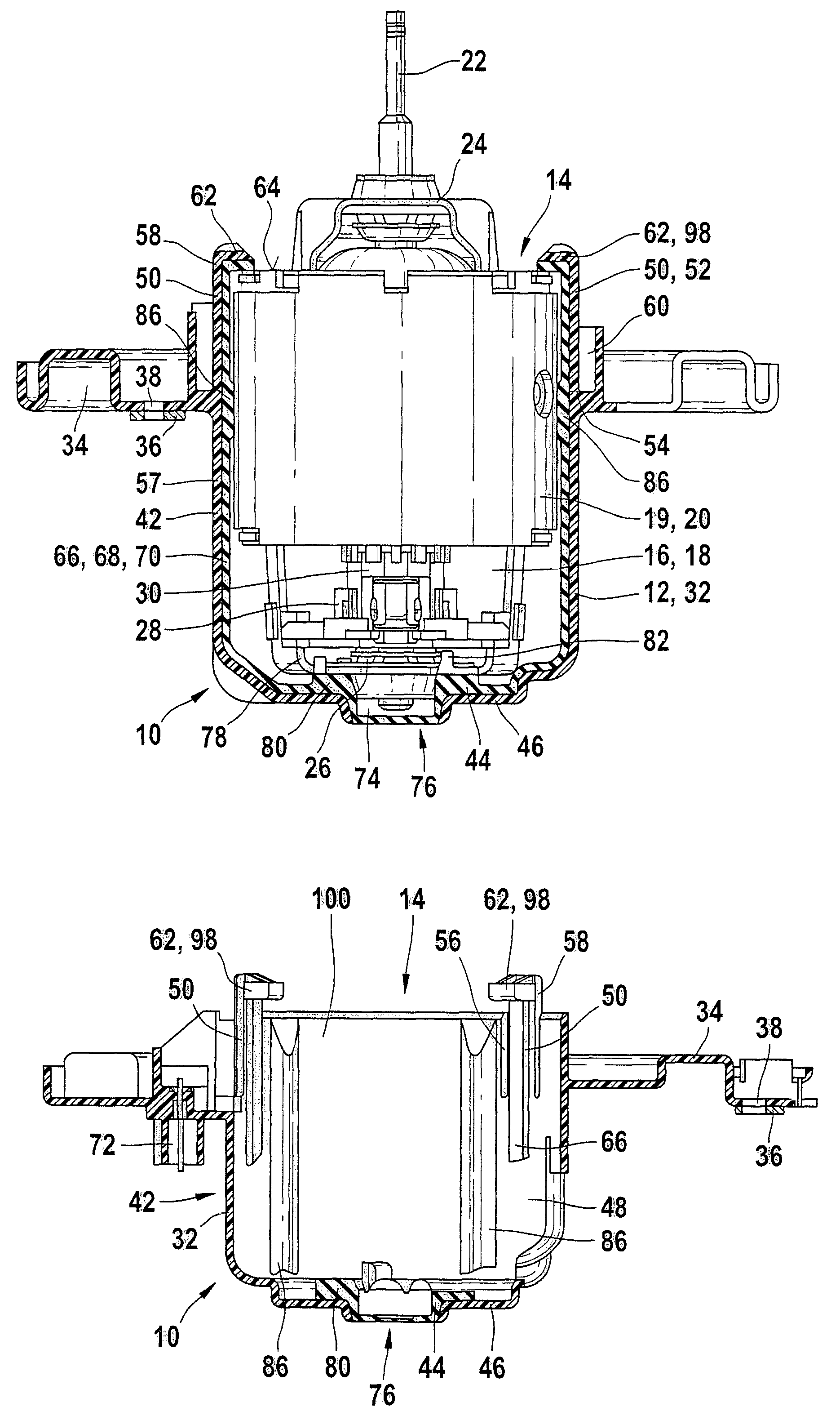
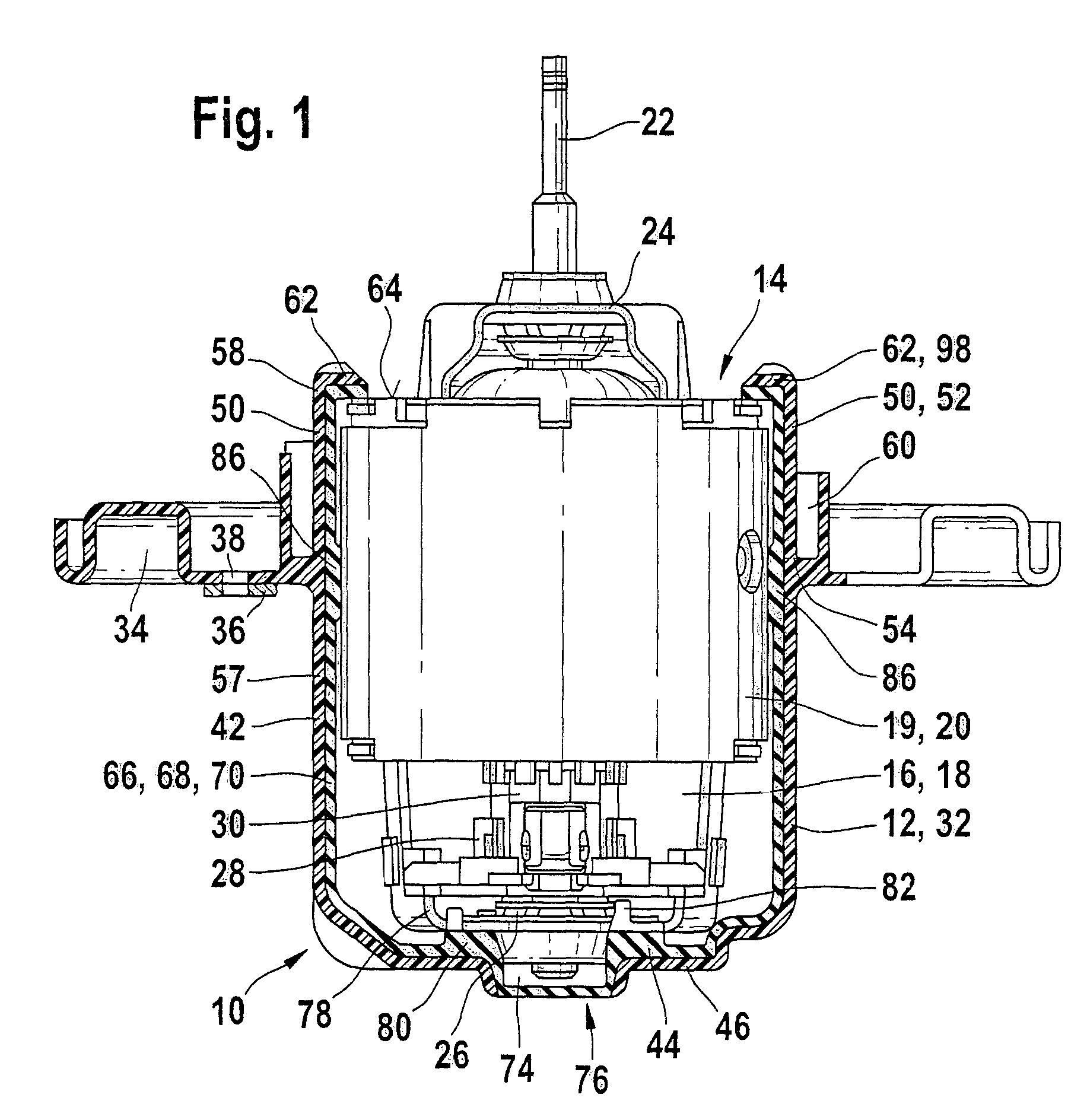
[0045]A first exemplary embodiment of the device 10 according to the invention is shown in FIG. 1. In this exemplary embodiment, the device 10 comprises a receptacle housing 12 with a receiving opening 14, through which a motor 16, in particular an electric motor 18, can be inserted in the housing 12. In the representation shown in FIG. 1, the electric motor 18 has already been completely inserted into the receptacle housing. In schematic fashion, shown in simplified form, the electric motor 18 [is equipped] with a pole ring 20—which simultaneously forms a pole housing 19—a motor shaft 22, a first bearing 24, and a second bearing 26 for holding the shaft 22, and a brush holder 28 with associated commutator 30.

[0046]A motor flange 34 is located on the outside of the receptacle housing 12 functioning as motor housing 32, which said motor flange is developed integral with the receptacle housing 12 in the exemplary embodiment in FIG. 1. Via this motor flange 34, the electric motor 18 ca...


PUM


Abstract

A device (10) for mounting an electric motor (18), in particular a fan motor, includes an essentially pot-shaped receptacle housing (12)—functioning as motor housing (32)—with a receiving opening (14) into which at least part of the electric motor (18) extends. A holding flange (34) is attached to the receptacle housing (12) for mounting the motor housing (32) to a carrier element (36), e.g., a motor vehicle heater system and / or air conditioner. A mechanism for immobilizing the electric motor (18) radially and axially in the motor housing (32) is included. The receptacle housing (12) includes at least one resilient-elastic holding element (50, 52, 90) for axial immobilization.

Description

BACKGROUND OF THE INVENTION[0001]The invention is based on a device for mounting an electric motor, in particular a fan motor, according to the preamble of the independent claim.[0002]Fan motors for heater and air-conditioner fan systems that are used in motor vehicles, for example, are usually decoupled from the vehicle in terms of vibration engineering in order to reduce a transfer of structure-borne noise from the motor and / or the fan unit to the vehicle body and, therefore, into the passenger compartment of the vehicle.[0003]Main sources of undesired vibrations, e.g., in DC motors, are imbalances in the motor and the commutation inside the motor. Commutation occurs when the copper windings of the armature conduct current while the motor is operating. During each rotation of the armature shaft, current flows through the windings in the motor once in each direction. The current flow in the windings, influenced by a permanent magnet field, produces a reaction that is transferred as...

Claims


Application Information

Patent Timeline
Patent Type & Authority Patents(United States)
IPC IPC(8): H02K5/00H02K5/24F04D29/62F04D29/66H02K5/08
CPCF04D29/626H02K5/24F04D29/668H02K5/08
Inventor GROSS, GERHARDSCHNEIDER, RALF-MICHAELNOLTING, PETERFRANK, WOLFGANG
Owner ROBERT BOSCH GMBH
Why Eureka
Try Eureka