
Duplexer and method of manufacturing same

Inactive Publication Date: 2006-07-18
SNAPTRACK
View PDF25 Cites 10 Cited by
  • Summary
  • Abstract
  • Description
  • Claims
  • Application Information

AI Technical Summary

Benefits of technology

[0009]It is an object of the invention to provide a duplexer capable of being fabricated through a smaller number of steps and a method of manufacturing such a duplexer.
[0012]According to the duplexer or the method of manufacturing the same of the invention, all of the thin-film piezoelectric resonators that the transmission filter and the reception filter include are disposed on the single base. As a result, according to the invention, the number of steps required for manufacturing the duplexer is smaller, compared to a duplexer manufactured through fabricating a chip including the transmission filter and a chip including the reception filter individually and mounting these chips on the packaging board.

Problems solved by technology

However, if the future mobile telecommunications devices are designed to be used at frequencies of 2 gigaherz and higher, there are still many technical problems to be solved to make surface acoustic wave filters capable of being used at such high frequencies.
The problem is that the method requires a number of steps to manufacture the duplexer.

Method used


Image

  • Duplexer and method of manufacturing same
  • Duplexer and method of manufacturing same
  • Duplexer and method of manufacturing same

Examples


first embodiment

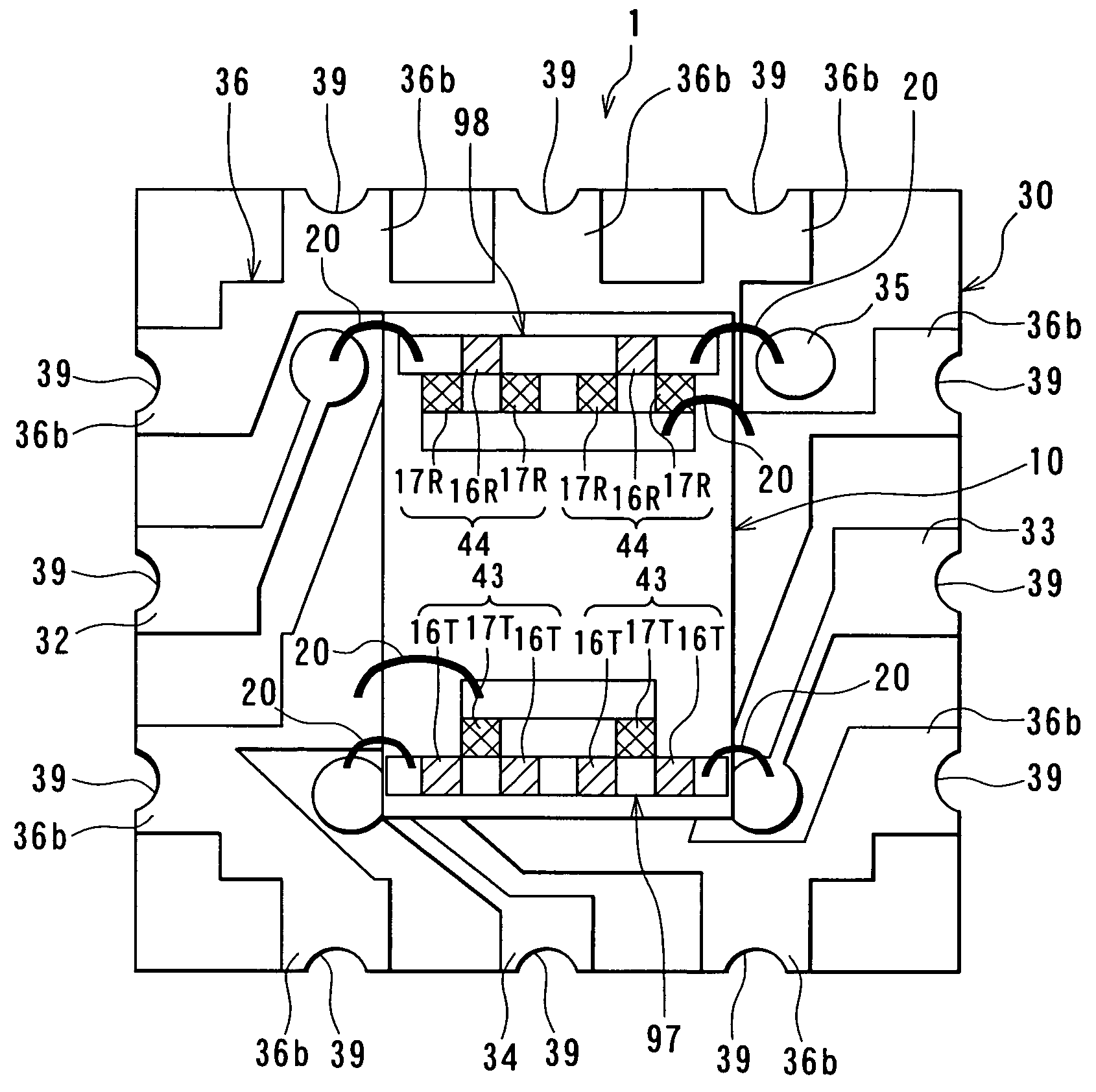
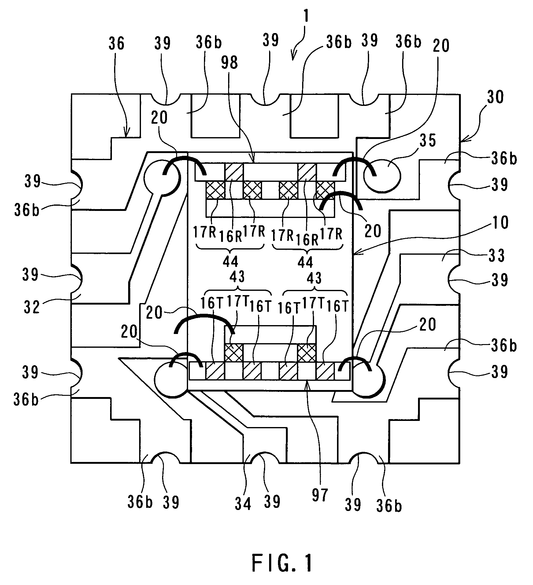
[0037]Reference is now made to FIG. 1 to describe the configuration of a duplexer of a first embodiment of the invention. FIG. 1 is a top view of the duplexer of the first embodiment.

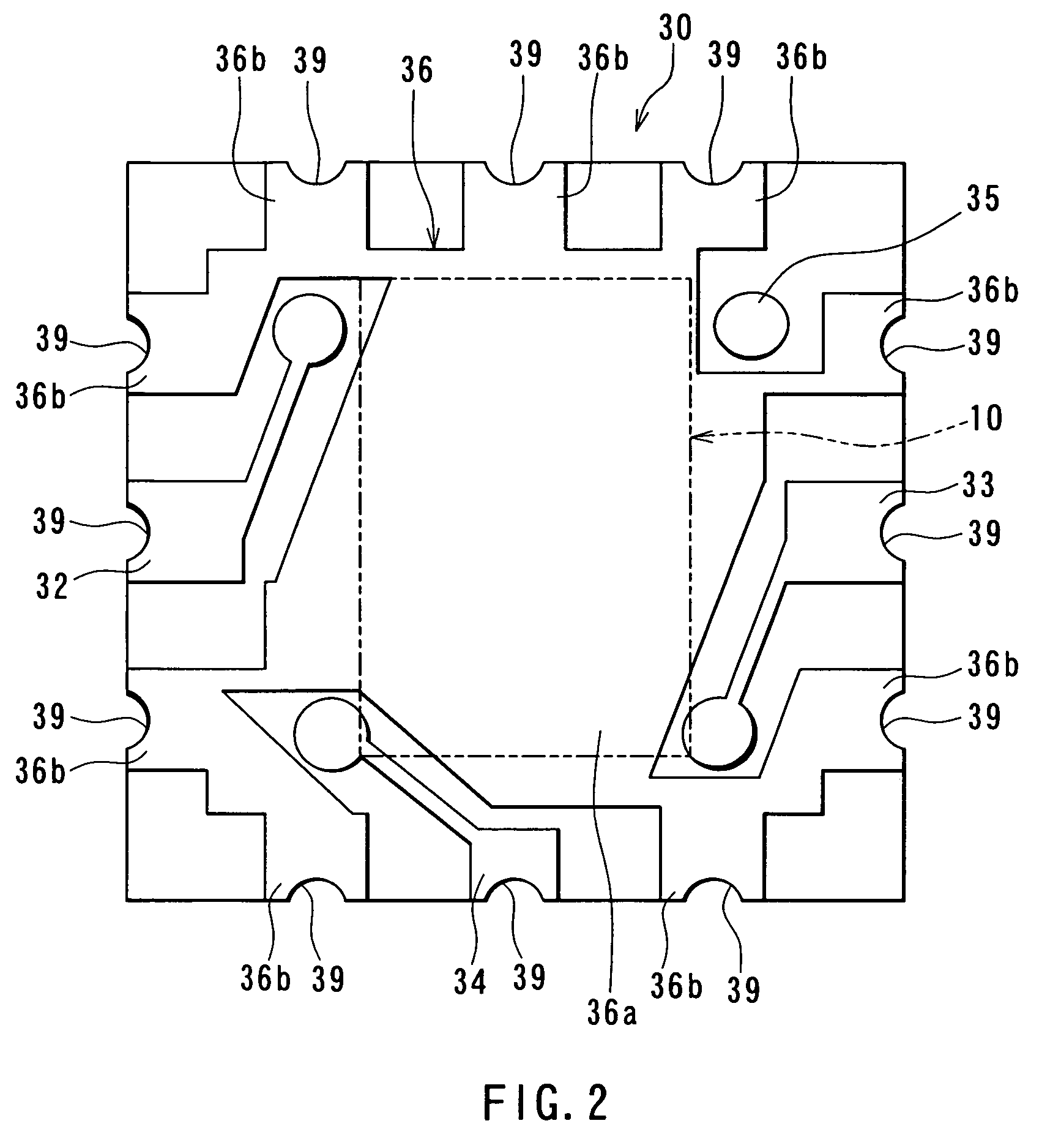
[0038]As shown in FIG. 1, the duplexer 1 of this embodiment comprises: a transmission filter 97 for allowing a transmission signal to pass therethrough and interrupting a reception signal; and a reception filter 98 for allowing a reception signal to pass therethrough and interrupting a transmission signal. The duplexer 1 is connected to an antenna that is not shown. Each of the transmission filter 97 and the reception filter 98 includes a plurality of thin-film piezoelectric resonators. The thin-film piezoelectric resonators that the transmission filter 97 and the reception filter 98 include are all disposed on a single base. A chip 10 including the transmission filter 97 and the reception filter 98 has such a configuration. The duplexer 1 comprises the chip 10 and a packaging board 30 on which the chip...

second embodiment

[0113]Reference is now made to FIG. 16 to describe a duplexer and a method of manufacturing the same of a second embodiment of the invention. FIG. 16 is a cross-sectional view that represents all of the thin-film piezoelectric resonators that the transmission filter 97 and the reception filter 98 of the embodiment include. In FIG. 16 numeral 13 represents the lower electrodes 13A to 13F, and numeral 15 represents the upper electrodes 15A to 15C. According to the duplexer of the second embodiment, each of the thin-film piezoelectric resonators that the transmission filter 97 and the reception filter 98 include has an acoustic multi-layer film 23 made up of a plurality of dielectric layers having different acoustic impedances. The acoustic multi-layer film 23 is disposed between the base 11 and each of the lower electrodes 13. In the second embodiment the base 11 has no cavity 11a.

[0114]The acoustic multi-layer film 23 is made up of first dielectric layers 23A made of a dielectric ma...


PUM


Abstract

A duplexer (1) comprises a chip (10) including a transmission filter (97) for passing a transmission signal therethrough and interrupting a reception signal and a reception filter (98) for passing a reception signal therethrough and interrupting a transmission signal. Each of the transmission filter (97) and the reception filter (98) includes thin-film piezoelectric resonators (16 and 17) each of which has a piezoelectric thin film that exhibits a piezoelectric property and two excitation electrodes that are disposed on both surfaces of the piezoelectric thin film and apply an excitation voltage to the piezoelectric thin film. All of the thin-film piezoelectric resonators (16 and 17) that the transmission filter (97) and the reception filter (98) include are disposed on a single base.

Description

TECHNICAL FIELD[0001]The present invention relates to a duplexer incorporating thin-film piezoelectric resonators and a method of manufacturing such a duplexer.BACKGROUND ART[0002]A reduction in size and an increase in usable frequency range have been sought for mobile telecommunications devices such as cellular phones that have been dramatically widespread. Accordingly, a reduction in size and an increase in usable frequency range have been desired for electronic components used in the mobile telecommunications devices, too.[0003]Some mobile telecommunications devices comprise a duplexer for switching between a transmission signal path and a receiver signal path, which allows a single antenna to be used for both transmission and reception. Such a duplexer comprises a transmission filter for allowing a transmission signal to pass therethrough and interrupting a reception signal and a reception filter for allowing a reception signal to pass therethrough and interrupting a transmissio...

Claims


Application Information

Patent Timeline
IPC IPC(8): H03H9/70H03H9/54H01L41/09H01L41/08H01L41/18H01L41/22H01L41/29H03H3/02H03H9/13H03H9/17H03H9/56H03H9/58H04B1/52
CPCH03H3/02H03H9/0571H03H9/132H04B1/52H03H9/564H03H9/568H03H9/706H03H9/175
Inventor KOMURO, EIJUGUNJI, KATSUHIKO
Owner SNAPTRACK
Learn More