Circularly polarized antenna and rectenna using this antenna
a technology of circular polarization and antenna, which is applied in the structural form of loop antenna, resonant antenna, radiating element, etc., can solve the problems of increasing the thickness of the whole of the prior art antenna element, difficult to thin the thickness of the dielectric board, etc., and achieves the reduction of the weight of the rectenna, and the simplified structure of the rectenna
- Summary
- Abstract
- Description
- Claims
- Application Information
AI Technical Summary
Benefits of technology
Problems solved by technology
Method used
Image
Examples
embodiment 1
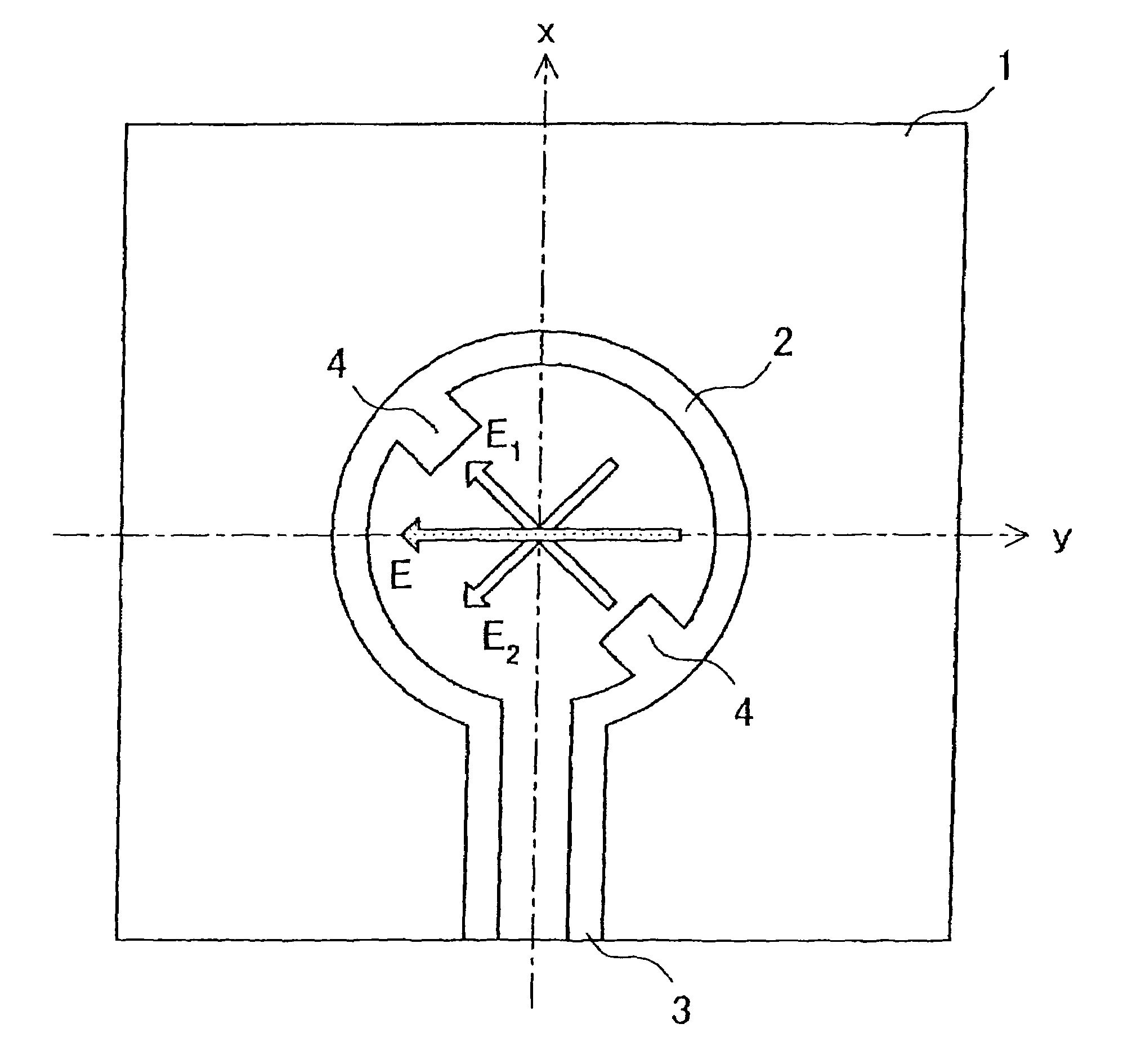
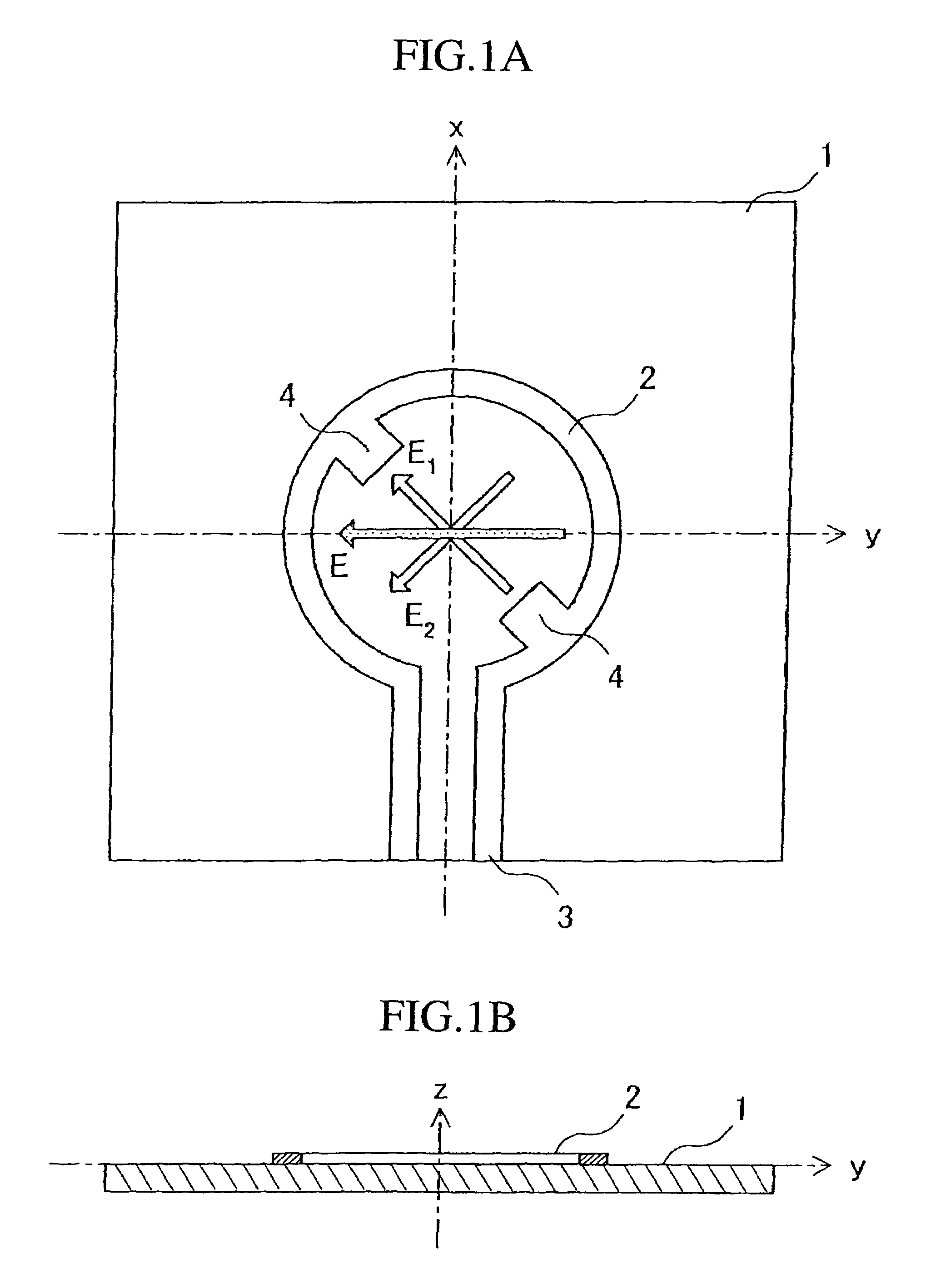
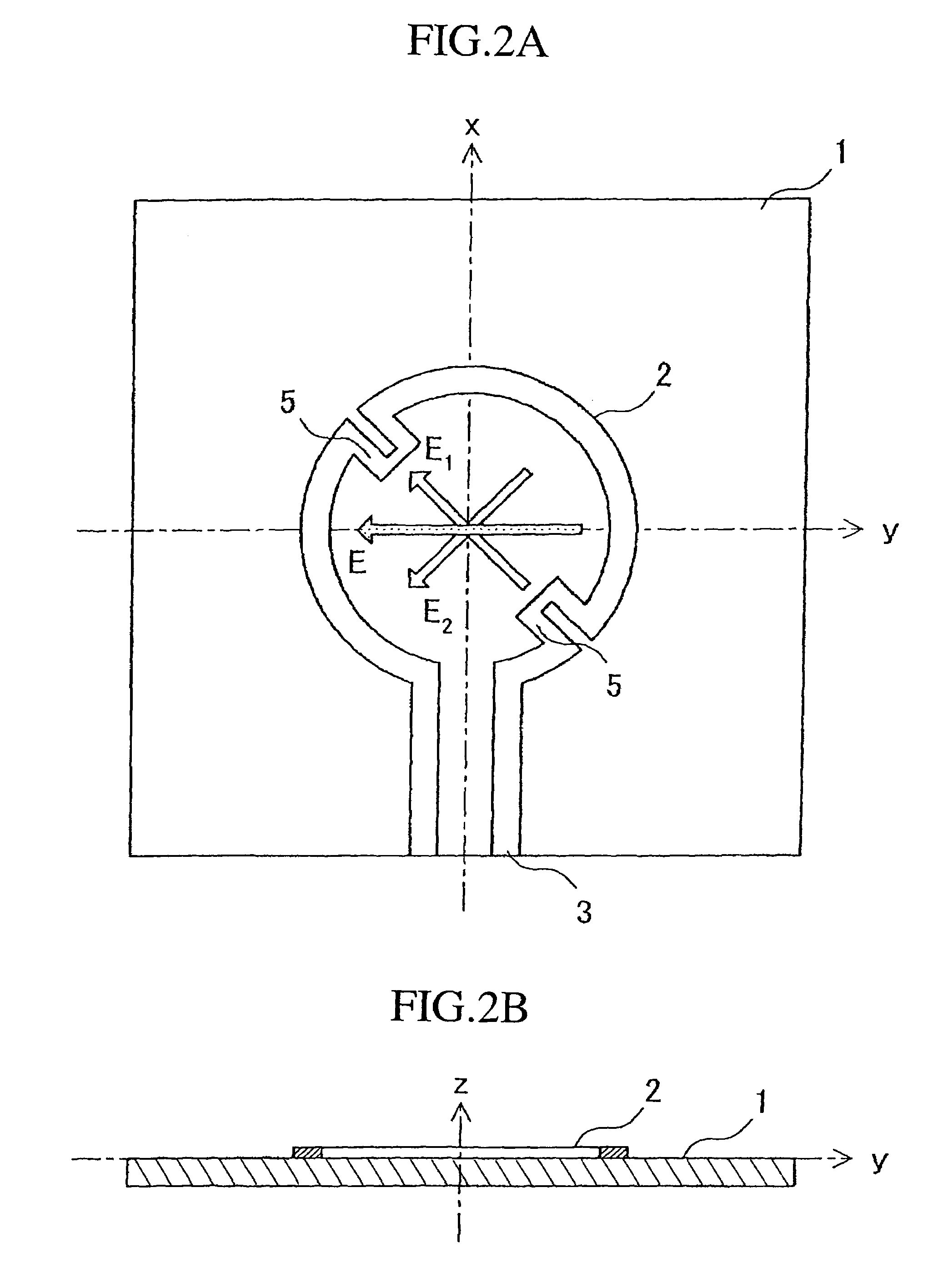
[0027]A circularly polarized antenna in accordance with embodiment 1 of the present invention will be explained with reference FIGS. 1 to 5. FIGS. 1A and 1B are views showing the structure of the circularly polarized antenna in accordance with embodiment 1 of the present invention. FIG. 1A is a front view of the circularly polarized antenna, and FIG. 1B is a cross-sectional view of the circularly polarized antenna. In FIG. 1A, reference numeral 1 denotes a dielectric board, reference numeral 2 denotes a loop antenna, reference numeral 3 denotes a balanced line, and reference numeral 4 denotes a perturbation element. The loop antenna unit 2, the balanced line 3, and two perturbation elements 4 are formed on the dielectric board 1 by using manufacturing methods, such as printing and etching. The loop antenna unit 2 is formed along the circumference of a circle, and is connected to the balanced line 3. Each of the two perturbation elements 4 is a member in the shape of a tooth which is...
embodiment 2
[0042]A rectenna element in accordance with embodiment 2 of the present invention will be explained with reference to FIGS. 6 and 7. FIG. 6 is a functional block diagram showing the functionality of the rectenna element in accordance with embodiment 2 of the present invention. In FIG. 6, reference numeral 10 denotes a microwave (i.e., RF electric power) space transmitted to the rectenna element, reference numeral 11 denotes a loop antenna unit, reference numeral 12 denotes a low pass filter (referred to as an LPF 12 from here on), reference numeral 13 denotes a rectifier circuit, reference numeral 14 denotes DC electric power outputted from the rectifier circuit 13, and reference numeral 15 denotes the rectenna element in which the loop antenna unit 11, the LPF 12, and the rectifier circuit 13 are connected in series. FIG. 7 is a diagram showing the structure of the rectenna element in accordance with embodiment 2 of present invention. As shown in FIG. 7, the loop antenna unit 11, t...
embodiment 3
[0045]A rectenna in accordance with embodiment 3 of the present invention will be explained with reference to FIGS. 8 and 9. FIG. 8 is a view showing the structure of the rectenna in accordance with embodiment 3 of the present invention. In FIG. 8, reference numeral 30 denotes a positive input terminal of a rectifier circuit of each of a plurality of rectenna elements 15, reference numeral 31 denotes a positive input terminal of the rectifier circuit of each of a plurality of rectenna elements 15, reference numeral 32 denotes a positive power feeding terminal which is disposed for feeding electric power into the plurality of rectenna elements 15, reference numeral 33 denotes a negative power feeding terminal which is also disposed for feeding electric power into the plurality of rectenna elements 15, reference numeral 34 denotes a strip line that connects the positive input terminals 30 of the plurality of rectenna elements 15 with the positive power feeding terminal 32, and referen...
PUM
 Abstract
Description
Claims
Application Information
 - R&D
- Intellectual Property
- Life Sciences
- Materials
- Tech Scout
- Unparalleled Data Quality
- Higher Quality Content
- 60% Fewer Hallucinations
Browse by: Latest US Patents, China's latest patents, Technical Efficacy Thesaurus, Application Domain, Technology Topic, Popular Technical Reports.
© 2025 PatSnap. All rights reserved.Legal|Privacy policy|Modern Slavery Act Transparency Statement|Sitemap|About US| Contact US: help@patsnap.com


