Optical disk data erasing apparatus and optical disk data erasing method
a technology of optical disk and data eraser, which is applied in the direction of digital signal error detection/correction, instruments, recording signal processing, etc., can solve the problems of insufficient reliability, difficult to erase written data from cd-r disk, and uncertain whether the disk is completely unplayable or not, so as to prevent leakage of secret information, reduce the cost, and eliminate recorded data. the effect of easy erasur
- Summary
- Abstract
- Description
- Claims
- Application Information
AI Technical Summary
Benefits of technology
Problems solved by technology
Method used
Image
Examples
embodiment 1
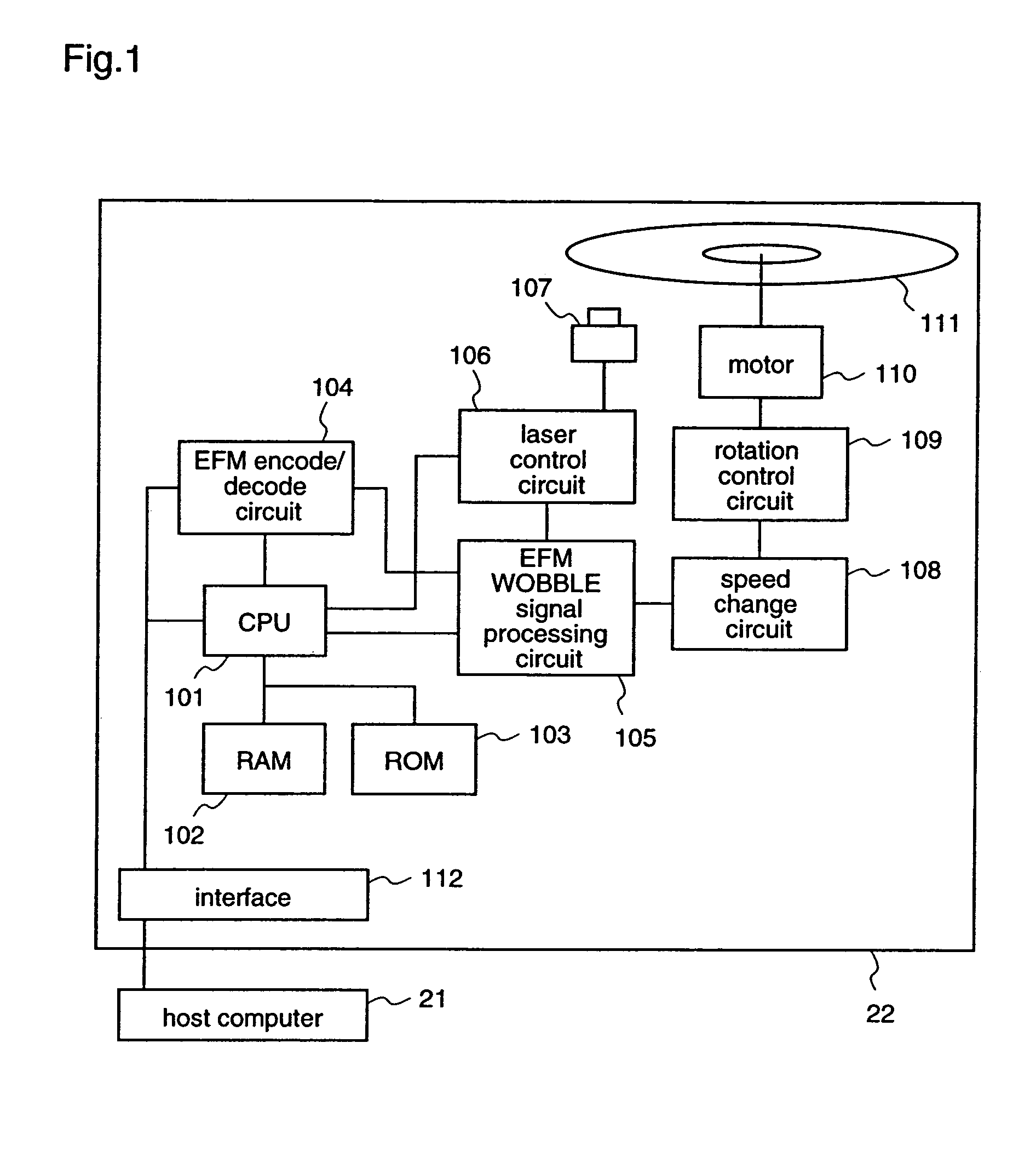
[0044]Hereinafter, an optical disk data erasing apparatus according to a first embodiment of the present invention will be described. FIG. 1 is a diagram illustrating the construction of an optical disk data erasing apparatus 22.
[0045]In FIG. 1, the optical disk data erasing apparatus 22 is an optical disk recording apparatus for writing or reading data in / from a recordable optical disk 111 by irradiating the optical disk with a laser beam. The optical disk data erasing apparatus 22 comprises a CPU 101, a RAM 102, a ROM 103, an EFM encoder / decoder circuit 104, an EFM WOBBLE signal processing circuit 105, a laser control circuit 106, a laser pickup 107, a speed change circuit 108, a rotation control circuit 109, and a motor 110.
[0046]The CPU 101 is provided with an instruction recognition means for recognizing an instruction from a host computer 21, and controls the respective constituents of the optical disk data erasing apparatus 22 according to a command from the ROM 103 or an ins...
embodiment 2
[0071]Hereinafter, an optical disk data erasing apparatus according to a second embodiment of the present invention will be described. FIG. 1 is a block illustrating the construction of an optical disk data erasing apparatus according to the second embodiment. FIG. 2 is a block diagram illustrating the construction of a data erasing system according to the second embodiment. FIG. 4 is a diagram illustrating an example of a disk format according to the second embodiment. Since FIGS. 1, 2, and 4 have already been described with respect to the first embodiment, repeated description is not necessary.
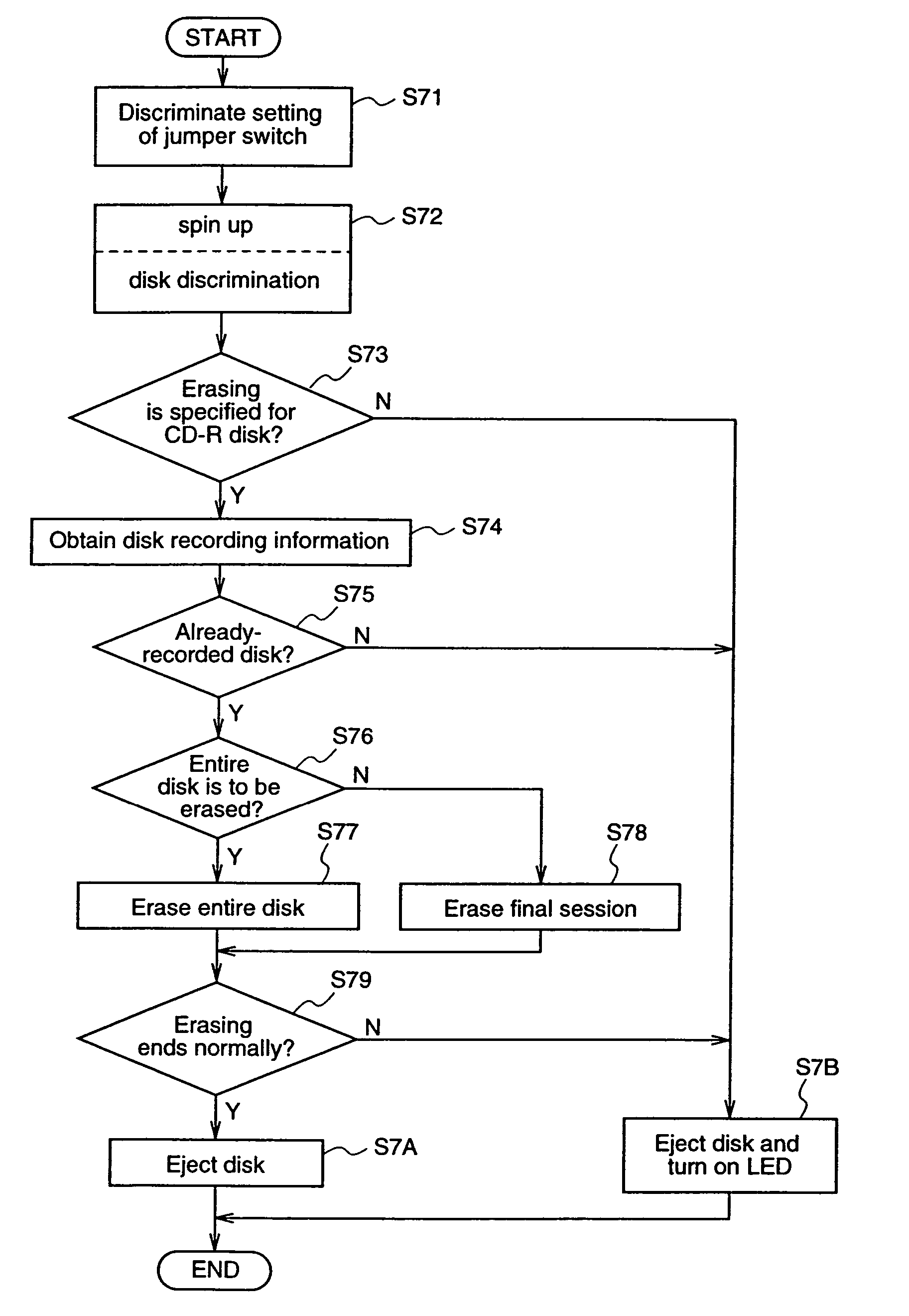
[0072]The optical disk data erasing apparatus 22 according to the second embodiment is provided with a judgement means for making a judgement as to whether the loaded optical disk 111 is a write-once optical disk (CD-R disk) or not; a disk recording information acquisition means for obtaining information relating to a data-recorded area or a data-unrecorded area (blank area) of the CD-R disk...
embodiment 3
[0088]Hereinafter, an optical disk data erasing apparatus according to a third embodiment of the present invention will be described. FIG. 1 is a block diagram illustrating the construction of an optical disk data erasing apparatus according to the third embodiment. Since FIG. 1 has already been described with respect to the first embodiment, repeated description is not necessary.
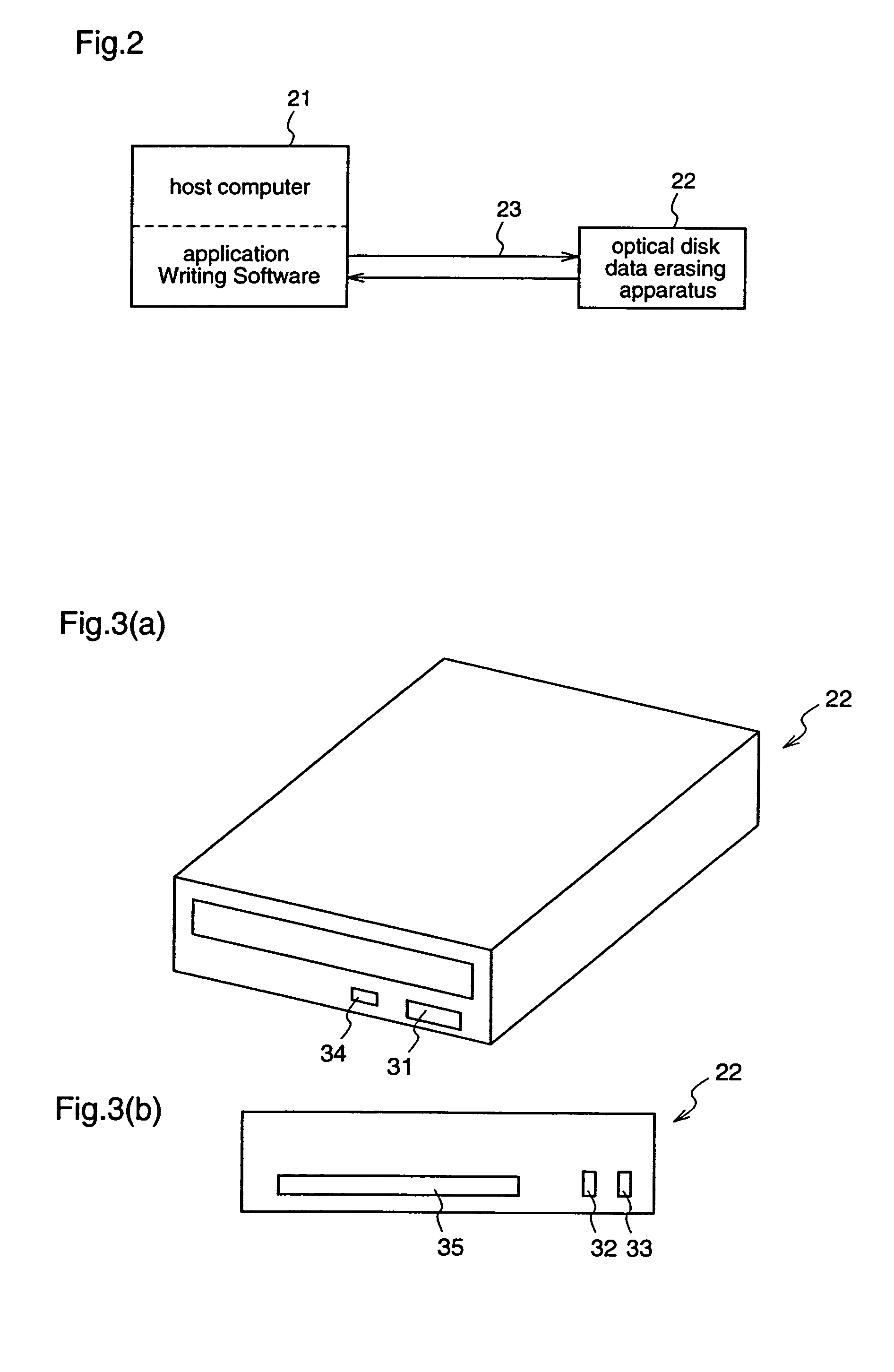
[0089]The optical disk data erasing apparatus 22 according to the third embodiment is provided with a first jumper switch setting means for setting ON / OFF of a first jumper switch 32; a second jumper switch setting means for setting ON / OFF of a second jumper switch 33; a setting distinguishing means for distinguishing whether the first jumper switch 32 and the second jumper switch 33 are ON or OFF; a judgement means for judging whether the loaded optical disk 111 is a CD-R disk or not; an erasing means for erasing recorded data, on the basis of the setting of the first and second jumper switches 32 and 33; ...
PUM
| Property | Measurement | Unit |
|---|---|---|
| recording power | aaaaa | aaaaa |
| area | aaaaa | aaaaa |
| temperature | aaaaa | aaaaa |
Abstract
Description
Claims
Application Information
 - R&D
- Intellectual Property
- Life Sciences
- Materials
- Tech Scout
- Unparalleled Data Quality
- Higher Quality Content
- 60% Fewer Hallucinations
Browse by: Latest US Patents, China's latest patents, Technical Efficacy Thesaurus, Application Domain, Technology Topic, Popular Technical Reports.
© 2025 PatSnap. All rights reserved.Legal|Privacy policy|Modern Slavery Act Transparency Statement|Sitemap|About US| Contact US: help@patsnap.com


