Heat sink, control device having the heat sink and machine tool provided with the device

a control device and heat sink technology, applied in semiconductor devices, lighting and heating apparatus, cooling/ventilation/heating modifications, etc., can solve the problems of reducing the amount of working fluid enclosed and the structurally useless portion of the sink, so as to reduce the structurally useless portion, reduce the weight of the heat sink, and reduce the cost

Inactive Publication Date: 2006-07-25
SHOWA DENKO KK
View PDF10 Cites 14 Cited by
  • Summary
  • Abstract
  • Description
  • Claims
  • Application Information

AI Technical Summary

Benefits of technology

[0021]If the height of the radiating fins in the lower region is thus made lower than the height of the radiating fins in the upper region, a further reduction can be made in the heat radiating area of the radiating fins present in the lower region having the circuit portion not contributing to heat radiation, consequently diminishing the structurally useless portion to result in a reduced cost and also contributing to a reduction in the weight of the heat sink. The pressure loss of the air flowing between the radiating fins can further be reduced to thereby achieve improved heat radiation performance.

Problems solved by technology

This diminishes the structurally useless portion of the sink, consequently serving to reduce the amount of working fluid to be enclosed in the circuit.

Method used


Image

  • Heat sink, control device having the heat sink and machine tool provided with the device
  • Heat sink, control device having the heat sink and machine tool provided with the device
  • Heat sink, control device having the heat sink and machine tool provided with the device

Examples


first embodiment

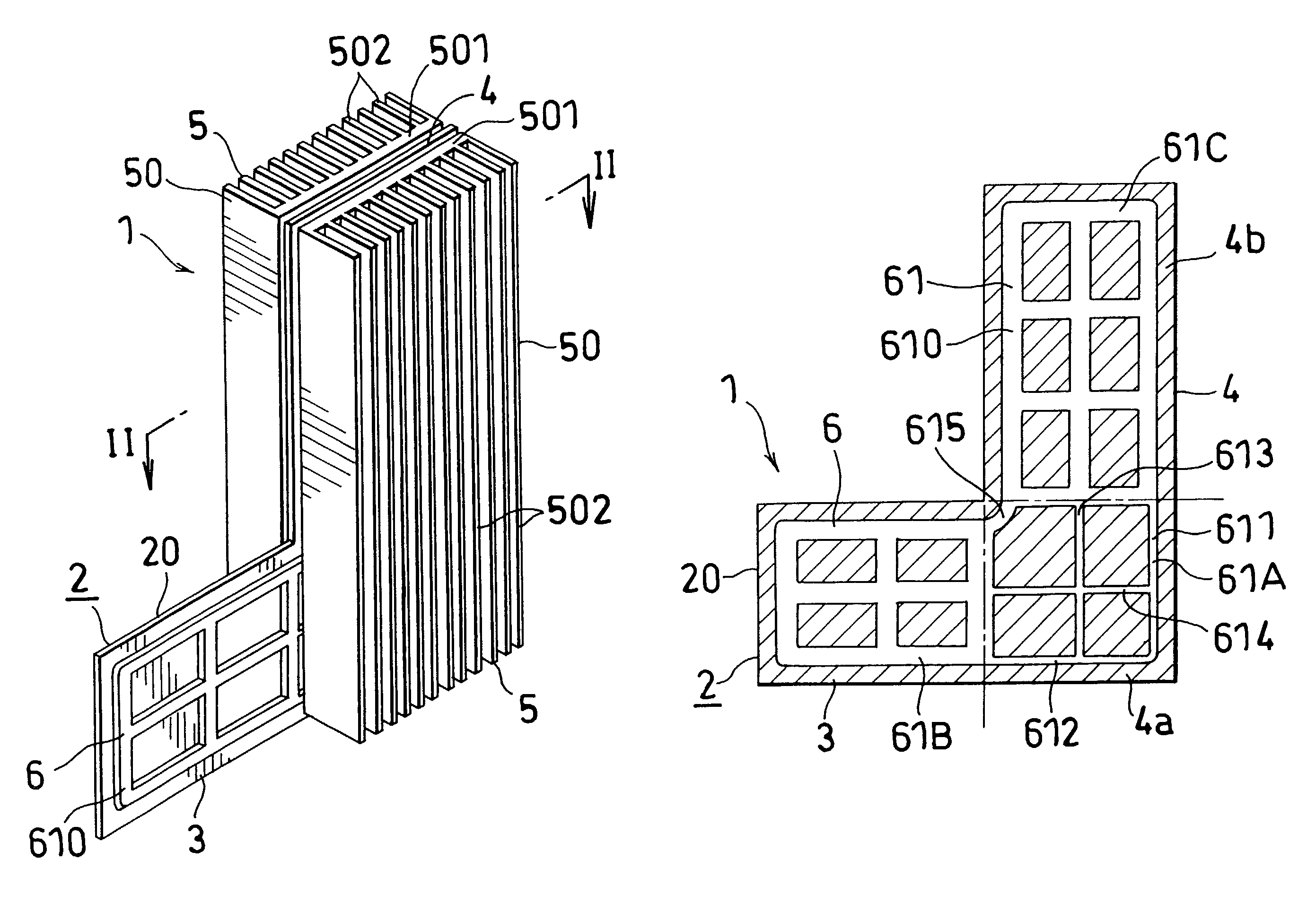
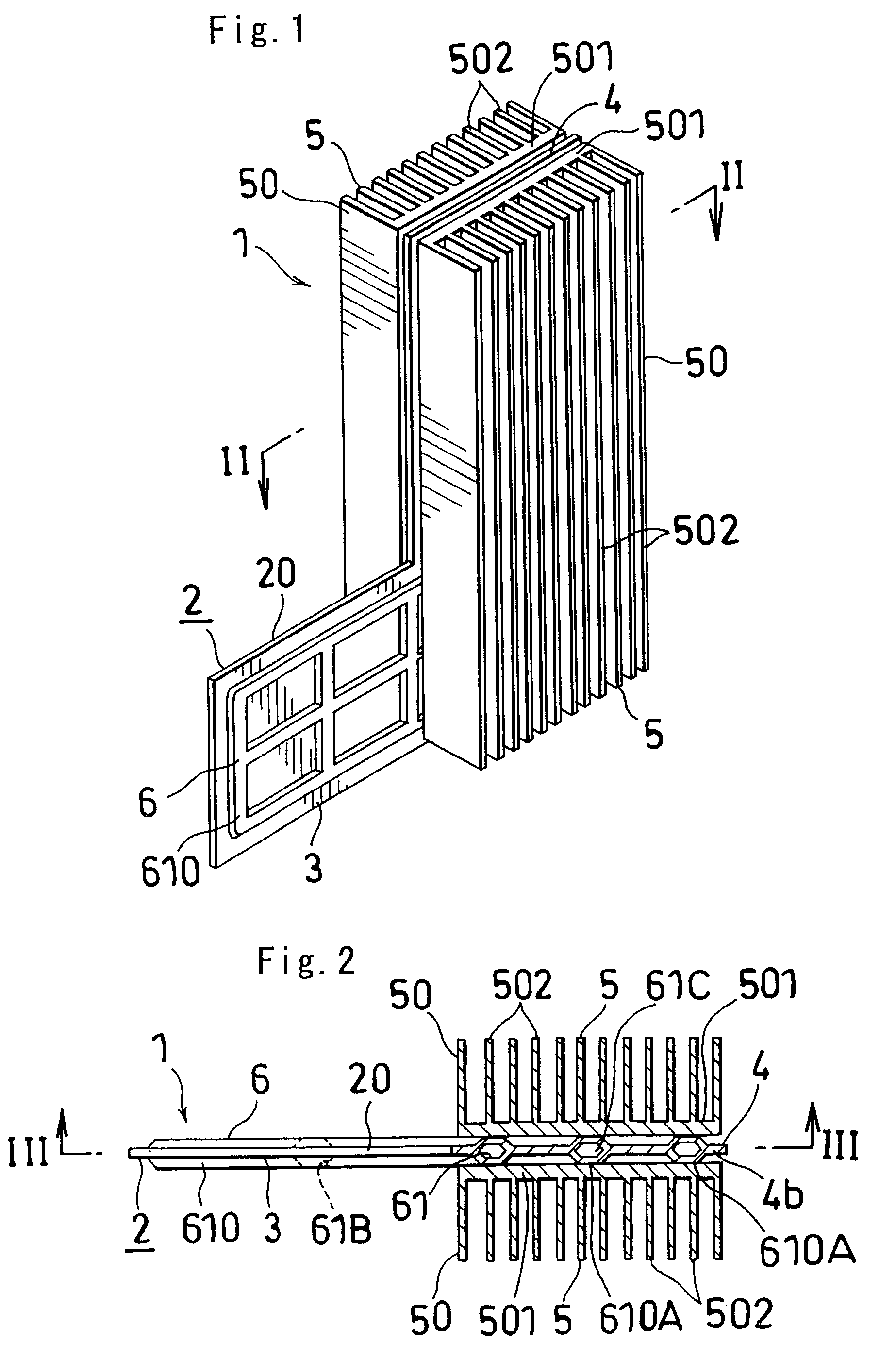
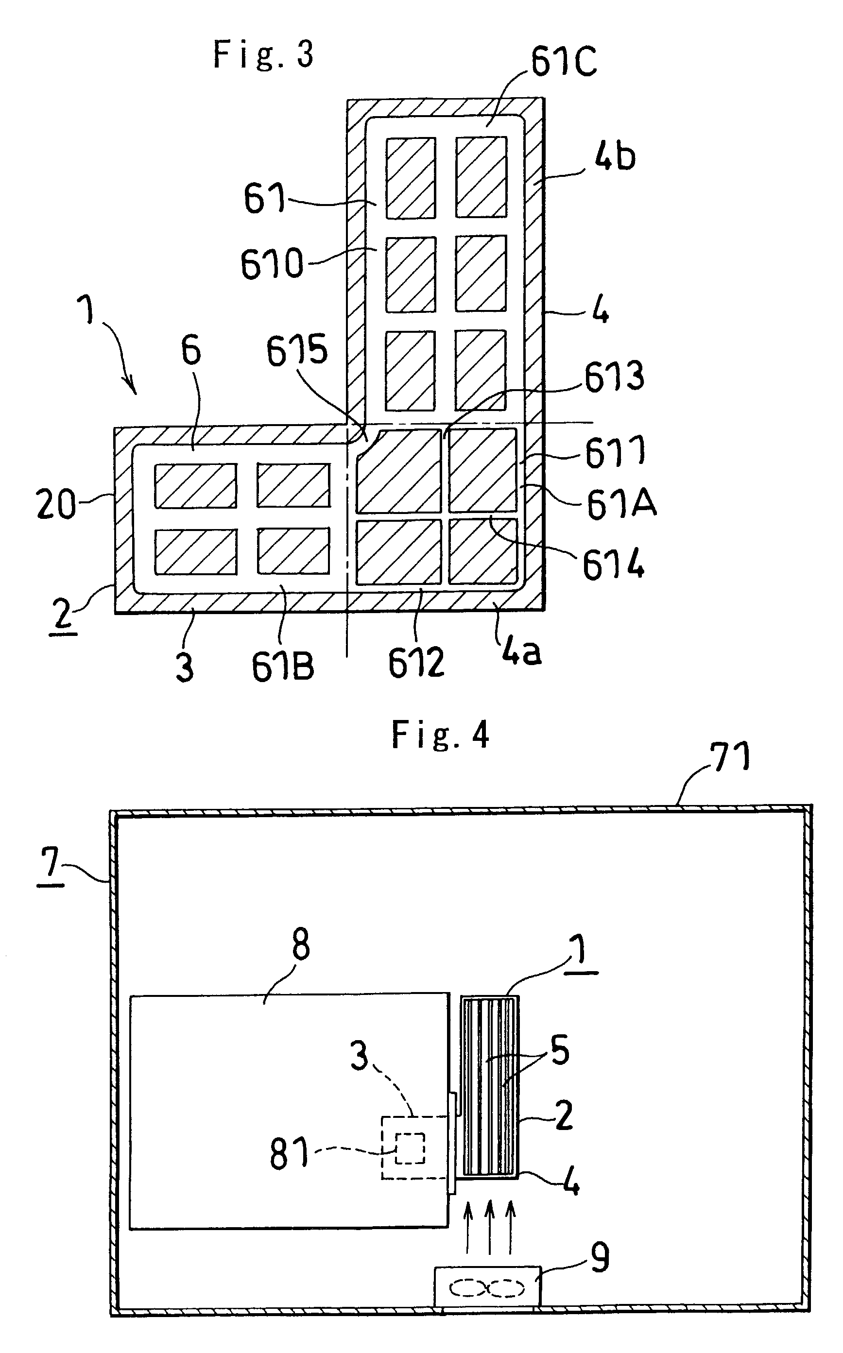
[0040]FIGS. 1 to 4 show the invention. With reference to FIGS. 1 to 3, a heat sink 1 of the invention comprises a heat sink main body 2 in the form of a vertical plate and having a heat receiving portion 3 and a heat radiating portion 4 integral with a lateral side of the heat receiving portion 3 and having an upper end projecting upward beyond the upper end of the portion 3, and radiating fins 5 provided on each of opposite surfaces of the heat radiating portion 4. The heat sink main body 2 has a heat pipe portion 6 which is formed by providing a working fluid circuit 61 extending from the heat receiving portion 3 to a lower region 4a of the heat radiating portion at the lateral side of the heat receiving portion 3 and further to an upper region 4b of the heat radiating portion which region 4b is positioned at a higher level than the heat receiving portion 3 and enclosing a working fluid (not shown) in the circuit 61. The portion 61A of the working fluid circuit provided in the low...

fourth embodiment

[0048]FIGS. 7 to 9 show the invention. These drawings show a heat sink 13, which comprises a heat sink main body 2 in the form of a vertical plate and having a heat receiving portion 3 and a heat radiating portion 4 integral with a lateral side of the heat receiving portion 3 and having an upper end projecting upward beyond the upper end of the portion 3, and radiating fins 5A provided on each of opposite surfaces of the heat radiating portion 4. The heat sink main body 2 has a heat pipe portion 6 which is formed by providing a working fluid circuit 61 extending from the heat receiving portion 3 to a lower region 4a of the heat radiating portion at the lateral side of the heat receiving portion 3 and further to an upper region 4b of the heat radiating portion which region 4b is positioned at a higher level than the heat receiving portion 3 and enclosing a working fluid (not shown) in the circuit 61. As shown in FIG. 9, the radiating fins 5A each have a lower end 500 positioned at a ...

fifth embodiment

[0053]FIGS. 10 to 12 show the invention. These drawings show a heat sink 14 which comprises a heat sink main body 2A in the form of a vertical plate and having a heat receiving portion 3 and a heat radiating portion 4 integral with a lateral side of the heat receiving portion 3 and having an upper end projecting upward beyond the upper end of the portion 3, and radiating fins 5B provided on one surface of the heat radiating portion 4. The heat sink main body 2A has a heat pipe portion 6 which is formed by providing a working fluid circuit 61 extending from the heat receiving portion 3 to a lower region 4a of the heat radiating portion at the lateral side of the heat receiving portion 3 and further to an upper region 4b of the heat radiating portion which region 4b is positioned at a higher level than the heat receiving portion 3 and enclosing a working fluid (not shown) in the circuit 61. As shown in FIG. 10, the fin pitch P1 of the radiating fins 5B in the lower region 4a of the he...


PUM


Abstract

A heat sink has a panel body and a heat radiating portion. The panel body includes a working fluid circuit for circulating a working fluid in the panel body and has a heat receiving portion and a heat radiating portion substantially on the same plane. The heat radiating portion has an upper region and a lower region. The heat receiving portion is provided on a lateral side of the lower region of the heat radiating portion, and a plurality of radiating fins are provided on at least one surface of the heat radiating portion of the panel body. The working fluid circuit extends from the heat receiving portion to the lower region of the heat radiating portion and further to the upper region of the heat radiating portion, and the working fluid circuit in the lower region of the heat radiating portion has an average channel cross sectional area which is smaller than an average channel cross sectional area of the working fluid circuit in the heat receiving portion.

Description

CROSS REFERENCE TO RELATED APPLICATIONS[0001]This application is an application filed under 35 U.S.C. 111(a) claiming the benefit pursuant to 35 U.S.C. 119(e)(1) of the filing date of Provisional Application No. 60 / 322,439 filed Sep. 17, 2001 pursuant to 35 U.S.C. 111(b).TECHNICAL FIELD[0002]The present invention relates to heat sinks, and more particularly to heat sinks of the heat pipe type suitable for cooling heat generating elements of control devices such as servoamplifiers for use in NC machine tools and like machine tools. The invention relates also to control devices equipped with the heat sink and machine tools provided with the device.BACKGROUND ART[0003]FIGS. 13 and 14 show a heat sink of the type mentioned already known which comprises a main body 102 in the form of a vertical plate and having a heat receiving portion 103 for receiving the heat from a heat generating element and a heat radiating portion 104 integral with a lateral side of the heat receiving portion 103 ...

Claims


Application Information

Patent Timeline
Patent Type & Authority Patents(United States)
IPC IPC(8): F28F7/00F28D15/00F28D15/02H05K7/20
CPCF28D15/0233H01L23/427H01L2924/0002H01L2924/00
Inventor OTA, KEIICHIROMARUGASA, SHIGEO
Owner SHOWA DENKO KK
Why Eureka
Try Eureka