ECM techniques to counter pulse compression radar

a pulse compression radar and pulse compression technology, applied in the field of electronic warfare (ew) systems, can solve the problems of ineffective radar system, complex ecm techniques to counter pulse compression radar systems, and inability of ecm devices to physically produce “n” signal pulses, and achieve the effect of increasing the jamming to signal power ratio

Active Publication Date: 2006-07-25
HARRIS CORP
View PDF8 Cites 30 Cited by
  • Summary
  • Abstract
  • Description
  • Claims
  • Application Information

AI Technical Summary

Benefits of technology

[0019]According to yet a further aspect of the present invention, positions of groups of the RFTs are placed ahead

Problems solved by technology

In the presence of a large number of ECM pulses a pulse tracker performing range tracking functions becomes overloaded with many ECM pulses that look like target echoes, thus rendering the radar system ineffective.
ECM techniques to counter pulse compression (PC) radar systems are more complex because a PC radar transmits long duration pulses.
The ECM devic

Method used


Image

  • ECM techniques to counter pulse compression radar
  • ECM techniques to counter pulse compression radar
  • ECM techniques to counter pulse compression radar

Examples


Embodiment Construction

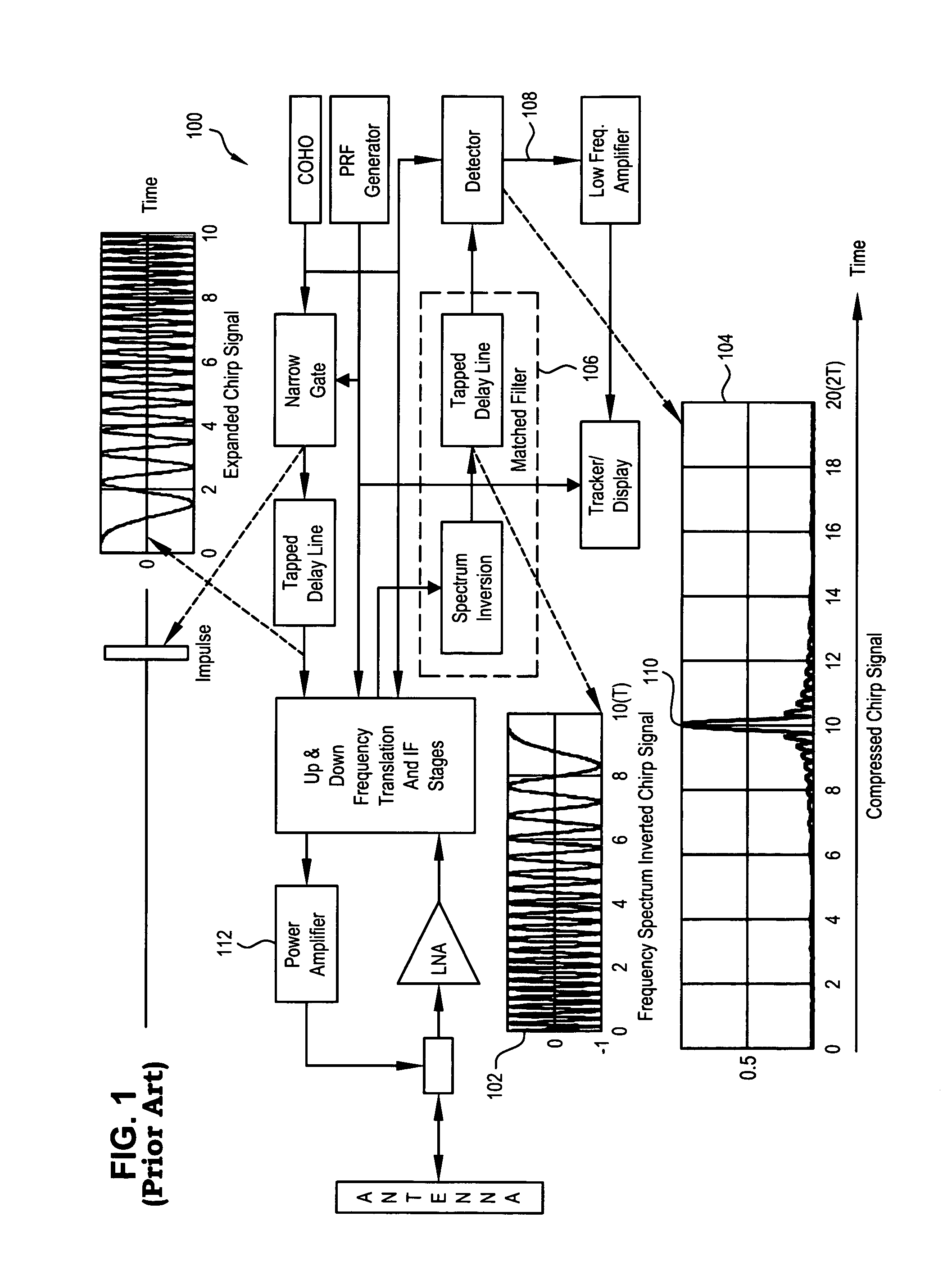
[0039]The design of an effective ECM technique must be based on PC signal characteristics that are altered. Just repeating the radar transmitted signal, as done in countering conventional pulsed radars, is not effective, because only one range false target is produced. In contrast, by altering the frequency modulation structure of the intercepted signal and returning it to the radar, a multi-lobe filter output is produced. The output can be made to look like a fence with protruding spikes, with minimum loss of signal power. If a LFM signal and wide bandwidth noise of equal power are applied to the matched filter, the matched filter output power is increased by a factor equal to the compression factor (PC), where PC=T / (1 / Δf)=TB, (defined by division of the pulse length at the filter input by the separation distance of 3 dB power points of the filter output). The noise signal power is increased only by PC1 / 2. Thus, in order to produce a multi-lobe filter output, the ECM signal must be...


PUM


Abstract

A system and method for generating a counter-measure signal in response to an incoming radar signal from a remote linear frequency modulated (LFM) pulse compression radar system. One method comprises the steps of receiving an incoming radar signal having a time period T; storing at least a portion of the radar signal in a memory; extracting predetermined segments of the radar signal from the memory; replicating the predetermined segments to create a predetermined plurality of each of the predetermined segments; concatenating the plurality of predetermined segments into a further signal, like ones of the plurality of predetermined segments adjacent one another; and transmitting the further signal to the remote radar system.

Description

FIELD OF THE INVENTION[0001]The present invention relates to Electronics Warfare (EW) Systems. More specifically, the present invention relates to signal modulation techniques for use in Electronic Countermeasure (ECM) systems for countering pulse compression radars.BACKGROUND OF THE INVENTION[0002]A radar is an electronic system that is designed to detect a target and measure the range, angle, and velocity of the target. It performs these functions by transmitting RF signal pulses through an antenna that focuses the energy into a narrow beam to illuminate the target. Range is calculated by measuring the elapsed time between the transmitted pulse and the target echo detected by the radar receiver.[0003]In a conventional Pulsed Doppler (PD) type radar, for example, the target radial velocity component is calculated from measurements of the difference frequency between the transmitted signal and its echo.[0004]Aircraft may be equipped with devices used to transmit RF ECM signals for t...

Claims


Application Information

Patent Timeline
IPC IPC(8): G01S7/38
CPCG01S7/38
Inventor SPARROW, MITCHELL JOSEPHCIKALO, JOSEPH
Owner HARRIS CORP
Why Eureka
Try Eureka