Compact optical tracking system for magnetic tape

Inactive Publication Date: 2006-07-25
ORACLE INT CORP
View PDF17 Cites 4 Cited by
  • Summary
  • Abstract
  • Description
  • Claims
  • Application Information

AI Technical Summary

Benefits of technology

[0009]A compact optical tracking system for magnetic tape is disclosed which is independent of the magnetic format and head structure, and which can generate a position error signal without encoding on the servo track. A plurality of optical servo modules are arranged in a linear array. Each optical servo module contains an optical beam source, preferably a laser, an optical beam interference composite hologram for producing a predetermined pattern on a target and at least one detector for detecting an optical beam reflection. A position correction signal is generated by one or all of the optical servo modules for re-positioning a magnetic head which reduces the error from tape dimensional changes. Reference gratings may be added to provide further position calibration prior to the tape being positioned over the head. In other embodiments, outboard optical heads are added for use with additional position references, which may include index marks for initial positioning in association with a desired servo track.

Problems solved by technology

As the width and spacing of the data tracks is decreased to increase capacity, it becomes more difficult to maintain the necessary positional accuracy using a narrower magnetic servo track.
If the width of the servo track is left wider to avoid this problem, some of the potential capacity increase is lost, and the head becomes more complex due to the unequal spacing of the elements.
For the magnetic tracking method to work with an unstructured single-element read head, complex encoding of the track and signal processing is required to extract a position error signal.
However, the large-scale optics required are difficult to implement in a small form factor drive, typically having limited space adjacent to the magnetic head.
Problems associated with the prior art include the continued need for a separate encoding head in order to accurately judge the position of the magnetic head relative to the tape guiding structure.
Other problems include inaccurate positioning of the tape head due to dirty or damaged servo tracks on the magnetic tape.
Still other problems with the prior art include focusing problems associated with the segmented detectors and slow response or positioning overshoot due to configurations which actuate more than just the mass of the magnetic head.

Method used


Image

  • Compact optical tracking system for magnetic tape
  • Compact optical tracking system for magnetic tape
  • Compact optical tracking system for magnetic tape

Examples


Embodiment Construction

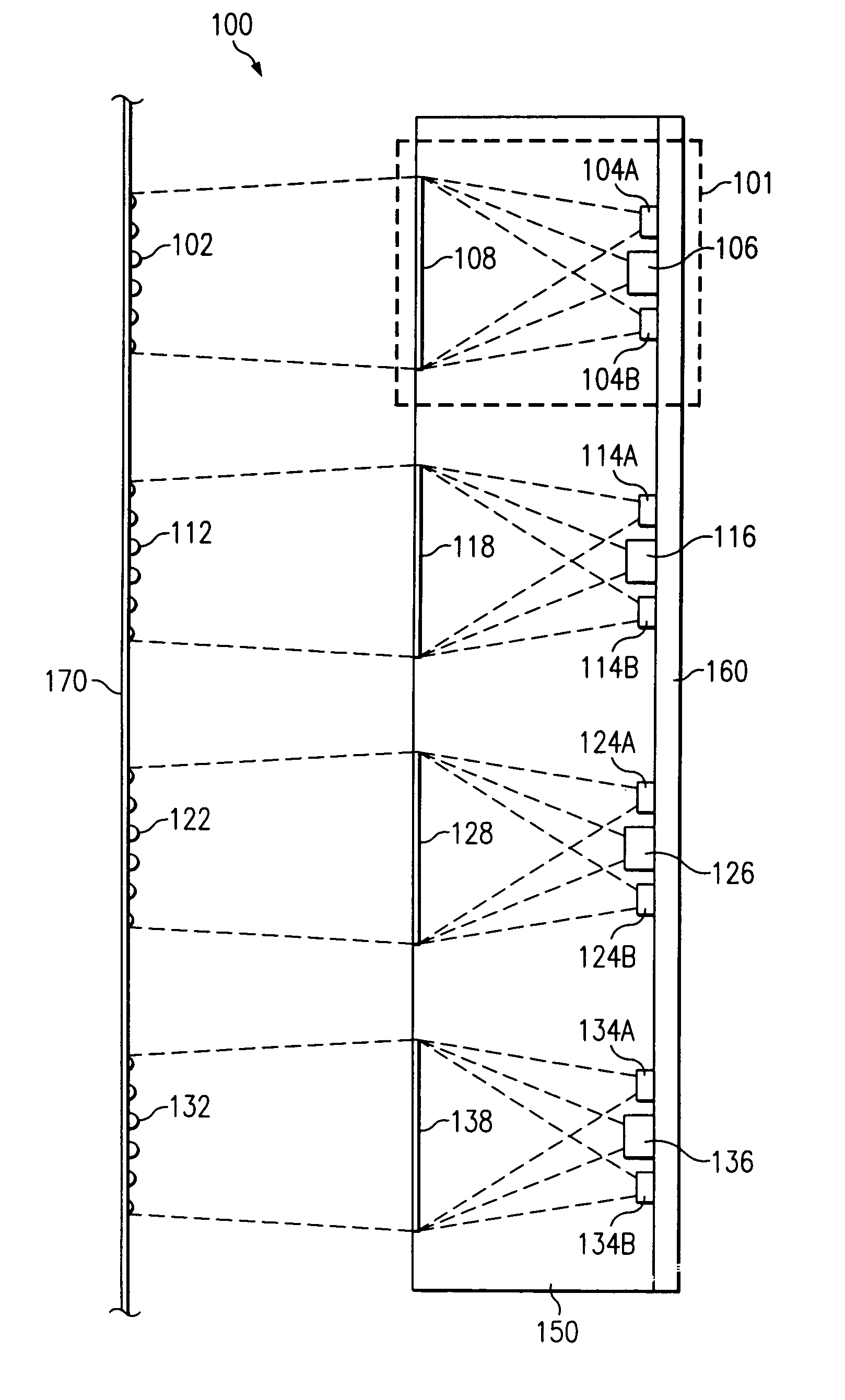
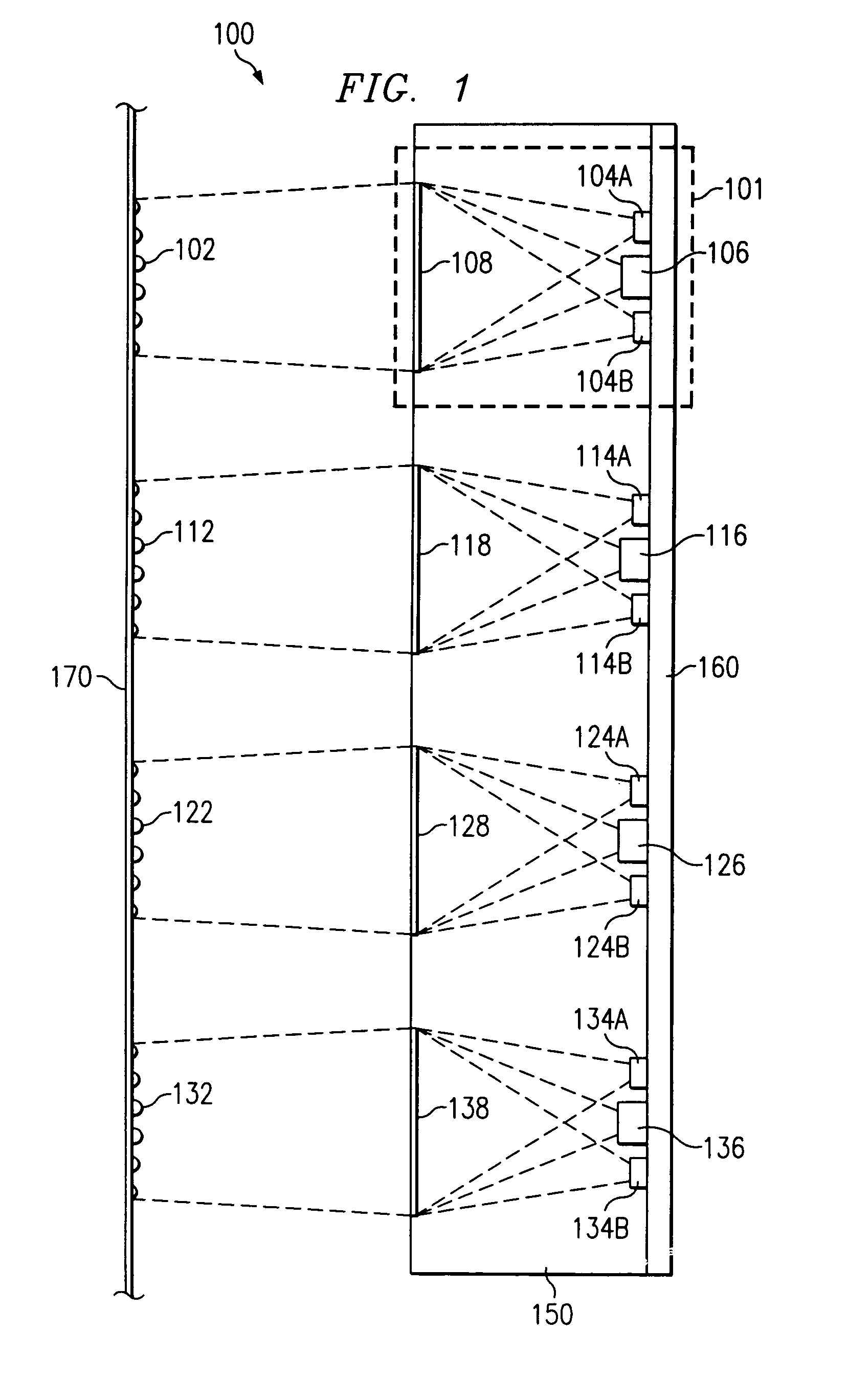
[0021]FIG. 1 is a schematic illustrating an optical servo module structure in accordance with a preferred embodiment of the present invention. Optical servo module structure 100 comprises a plurality of servo modules in a linear array. Servo module 101 is typical of the servo modules contained in optical servo module structure 100. Servo module 101 contains laser source 106 and detectors 104A and 104B, which are formed in or mounted on substrate 160. Clear plastic block 150 is formed over laser source 106, detectors 104A and 104B, and substrate 160. Composite hologram 108 is formed in or added to clear plastic block 150, approximately perpendicular to the direction of the optical beam projected from laser source 106. The servo modules in optical servo module structure 100 may be independent modules mechanically assembled together to form a single optical servo module structure. However, in a preferred embodiment of the present invention, the individual servo modules are formed toget...


PUM


Abstract

A compact optical tracking system for magnetic tape is disclosed which is independent of the magnetic format and head structure which can generate a position error signal without encoding on the servo track. A plurality of optical servo modules is arranged in a linear array. Each optical servo module contains an optical beam source, preferably a laser, an optical beam interference composite hologram for producing a predetermined pattern on a target and at least one detector for detecting an optical beam reflection. A position correction signal is generated by one or all of the optical servo modules for re-positioning a magnetic head, which reduces the error in the correction signal from tape degradation and dimensional changes. Reference grating may be added to provide further position calibration prior to the tape being positioned over the head. Refinements to the tracking system include outboard heads which are added for additional position references and which may include index marks for initial positioning in association with a desired servo track.

Description

BACKGROUND OF THE INVENTION[0001]1. Technical Field[0002]The present invention relates to the field of magnetic tape drives. More particularly, the present invention relates to positioning a magnetic head for proper pickup of information tracks on a magnetic tape or disk.[0003]2. Description of Related Art[0004]In magnetic tape drive technology, it is known to employ a tracking servo system to follow pre-written servo tracks on the magnetic tape to accurately position the magnetic heads. Typically, one or more read heads are dedicated to sensing the servo tracks and are added to or interleaved with the data read heads. For example, a combination head with 18 side-by-side data heads may include two or three servo read heads to assure accurate positioning. As the width and spacing of the data tracks is decreased to increase capacity, it becomes more difficult to maintain the necessary positional accuracy using a narrower magnetic servo track. If the width of the servo track is left wi...

Claims


Application Information

Patent Timeline
IPC IPC(8): G11B5/58G11B5/584G11B5/596G11B5/55
CPCG11B5/584G11B5/5504
Inventor SMITH, ARCHIBALD W.
Owner ORACLE INT CORP
Why Eureka
Try Eureka