Optical recording apparatus with drawing capability of visible image on disk face

a recording apparatus and optical technology, applied in recording apparatus, optical beam sources, instruments, etc., can solve the problem of complicated handling and perform the effect of recording

Inactive Publication Date: 2006-07-25
YAMAHA CORP
View PDF11 Cites 41 Cited by
  • Summary
  • Abstract
  • Description
  • Claims
  • Application Information

AI Technical Summary

Benefits of technology

[0007]To resolve this problem, it is one objective of the present invention to provide an optical disk recording apparatus that can not only record data on the recording face of an optical disk, but can also draw an image to a thermo sensitive face of the disk for the visual representation of content information without a new apparatus having to be separately prepared.

Problems solved by technology

Therefore, after data has been recorded to the recording face of a specific disk using an optical disk recording apparatus, complicated handling must be performed after the optical disk is ejected from the optical disk recording apparatus.

Method used


Image

  • Optical recording apparatus with drawing capability of visible image on disk face
  • Optical recording apparatus with drawing capability of visible image on disk face
  • Optical recording apparatus with drawing capability of visible image on disk face

Examples


modification 1

(Modification 1)

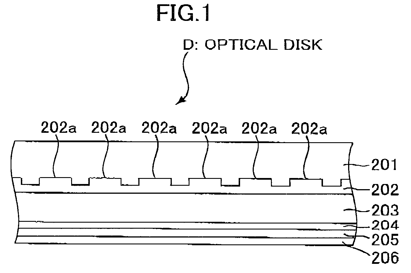
[0131]In the above embodiment, in accordance with the gradation level for each coordinate point that is included in image information received from the host PC 110 in consonance with a visual image, the laser irradiation period is controlled so as to express the density of the visual image formed on the thermo sensitive face of the optical disk D. However, information indicating the gradation level of each coordinate point may be employed to change the write level of the laser power, and the density of a visual image may be expressed. For example, as is shown in FIG. 19, when the thermo sensitive face (photosensitive layer 205: see FIG. 1) of the optical disk D has a characteristic according to which the discoloration level is moderately changed in accordance with the amount of thermal energy applied thereto, the discoloration level of the thermo sensitive face is changed to D1, D2 or D3 by the application of different amounts of energy, such as E1, E2 or E3. Therefo...

modification 2

(Modification 2)

[0138]In the above described embodiment, when a visual image has been formed by emitting the laser beam while the optical disk D is rotated once from the reference position, the feeding control process is performed, i.e., the optical pickup 10 is moved a predetermined distance in the outer direction of the diameter, and the laser irradiation position is moved very near the surface of the optical disk D. However, some mechanisms for driving the optical pickup 10 in the direction of the diameter can not control the travel distance represented by units of 20 μm. For an optical disk recording apparatus wherein such a driving mechanism is mounted, the size of a portion on the optical disk that the laser beam can not radiate is increased, and as a result, the quality of a visual image formed on the thermo sensitive face is deteriorated.

[0139]When the adjustability of the drive means for moving the optical pickup 10 in the direction of the diameter is low, the control by th...

modification 3

(Modification 3)

[0141]The optical disk recording apparatus 100 for the above embodiment employs the CAV method whereby, for forming a visual image, a laser beam is emitted while the optical disk D is rotated at a consistent angular velocity. However, the CLV method whereby the linear velocity is consistent may be employed. When the CAV method is employed, in order to obtain a visual image having a high quality, the write level value for the laser beam should be increased as the laser irradiation position is moved outward across the optical disk D; however, when the CLV method is employed, the write level value need not be changed. Therefore, the quality of an image formed on the thermo sensitive face of the optical disk will not be deteriorated due to the fluctuation of the target laser power value.


PUM

PropertyMeasurementUnit
diameter BSaaaaaaaaaa
diameteraaaaaaaaaa

Abstract

An optical disk apparatus records information by irradiating a laser beam from a pickup onto an optical disk. A scanning section scans the laser beam relative to the optical disk. A recording control section controls the scanning section to effect recording of information. A drawing control section is provided for controlling the pickup and the scanning section to effect drawing of a visible image on the optical disk according to image information, such that the laser beam is changed between a first intensity incapable of acting on the optical disk and a second intensity capable of acting on the optical disk. A servo section periodically detects the laser beam reflected back from the optical disk when the laser beam has the first intensity, and servo-controls the irradiating of the laser beam during the drawing of the visible image based on the detection of the laser beam. The drawing control section controls the pickup for forcibly changing the laser beam to the first intensity from the second intensity when the second intensity is maintained over a predetermined period pursuant to the image information, thereby enabling the servo section to detect the laser beam having the first intensity for continuing the servo-control.

Description

BACKGROUND OF THE INVENTION[0001]1. Field of the Invention[0002]The present invention relates to an optical disk recording apparatus that can form a visual image on the face of an optical disk.[0003]2. Description of Prior Art[0004]Recordable optical disks, such as a CD-R (Compact Disk-Recordable) and a CD-RW, are available on the market. To record a variety of data, such as music data, on these optical disks, optical disk recording apparatuses, such as CD-R drives and CD-RW drives, are employed. For recording information, one of these optical disk recording apparatuses emits a laser beam, which is modulated to correspond to the information that is to be recorded and which impinges on the recording face of an optical disk.[0005]For some types of optical disks, printed labels for the visual presentation of content information, such as titles and brief descriptions of recorded music or other recorded data, are affixed to the other disk face opposite to the data recording side. During ...

Claims


Application Information

Patent Timeline
Patent Type & Authority Patents(United States)
IPC IPC(8): G11B7/00G11B7/0037G11B7/0045G11B7/007G11B7/125G11B23/30G11B23/40
CPCG11B7/0037G11B7/0045G11B23/40G11B7/1263G11B7/24094G11B19/122G11B23/30G11B7/0908G11B7/00455G11B7/00736G11B7/08505G11B7/08582G11B7/0945
Inventor MORISHIMA, MORITOUSUI, AKIRASHIOZAKI, YOSHIHIKO
Owner YAMAHA CORP
Why Eureka
Try Eureka