Vehicular information and monitoring system and methods

a technology of information and monitoring system, applied in the field of vehicle information and monitoring system and methods, can solve the problems of deterioration of other components of the vehicle, frequent minimal repair cost, and gradual failure of water pump, and achieve the effect of reducing injuries

Inactive Publication Date: 2006-07-25
AMERICAN VEHICULAR SCI
View PDF85 Cites 316 Cited by
  • Summary
  • Abstract
  • Description
  • Claims
  • Application Information

AI Technical Summary

Benefits of technology

[0081]A method for information management and monitoring of a plurality of vehicles in accordance with the invention is designed for manufacturers and other parties interested in statistical failure of vehicle components and includes arranging a vehicle monitoring system including a plurality of sensors on each vehicle to monitor components of the vehicle, arranging a diagnostic module on each vehicle, directing data about the monitored components from the vehicle monitoring system to the diagnostic module for analysis and processing thereby, coupling a communication system on each vehicle to the diagnostic module, establishing communications between the diagnostic module and a data gathering facility which accumulates information about the failure rate of the components to enable transmission of data between the diagnostic module and the data gathering facility such that the data gathering facility receives data about the monitored components of the vehicle, and accumulating data from the vehicle at the data gathering facility to enable calculation of statistics about failure rate of the components.
[0086]3. To provide an early warning of a potential component failure and to thereby minimize the cost of repairing or replacing the component.
[0088]5. To provide a device that uses information from existing sensors for new purposes thereby increasing the value of existing sensors and, in some cases, eliminating the need for sensors that provide redundant information.
[0095]1. To utilize pattern recognition techniques and the output from multiple sensors to determine at an early stage that a vehicle rollover might occur and to take corrective action through control of the vehicle acceleration, brakes and steering to prevent the rollover or if it is preventable, to deploy side head protection airbags to reduce the injuries.

Problems solved by technology

When a vehicle component begins to fail, the repair cost is frequently minimal if the impending failure of the component is caught early, but increases as the repair is delayed.
Sometimes, if a component in need of repair is not caught in a timely manner, the component, and particularly the impending failure thereof, can cause other components of the vehicle to deteriorate.
One example is where the water pump fails gradually until the vehicle overheats and blows a head gasket.
Another example is when a tire gradually loses air until it heats up, fails and causes an accident.
In these cases, the warning often comes too late as most vehicle gages alert the driver after he or she can conveniently solve the problem.
Other drivers can sense that their vehicle is performing differently but they don't know why or when a component will fail or how serious that failure will be, or possibly even what specific component is the cause of the difference in performance.
There are no systems currently on automobiles to monitor the numerous vehicle components over time and to compare component performance with normal performance.
Additionally, there is no system currently existing on a vehicle to look for erratic behavior of a vehicle component and to warn the driver or the dealer that a component is misbehaving and is therefore likely to fail in the very near future.
Sometimes, when a component fails, a catastrophic accident results.
Similarly, other component failures can lead to loss of control of the vehicle and a subsequent accident.
The system of this patent does not predict or warn the operator or the home base of a pending problem.
This system only reports failures after they have occurred and does not predict them.
In this case, the signal from the manifold absolute pressure sensor may be indicative of a fault in the intake of air into the engine, e.g., the engine is drawing in too much or too little air, and is thus affected by the operation of the engine.
However, the system of Marko et al. does not detect faults in the sensors that are conducting the measurements, e.g., a fault in the exhaust gas oxygen sensor, or faults that are only developing but have not yet manifested themselves or faults in other systems.
Every automobile driver fears that his or her vehicle will break down at some unfortunate time, e.g., when he or she is traveling at night, during rush hour, or on a long trip away from home.
However, vehicles perform such monitoring typically only for the vehicle driver and without communication of any impending results, problems and / or vehicle malfunction to a remote site for trouble-shooting, diagnosis or tracking for data mining.
In the past, systems that provide for remote monitoring did not provide for automated analysis and communication of problems or potential problems and recommendations to the driver.
As a result, the vehicle driver or user is often left stranded, or irreparable damage occurs to the vehicle as a result of neglect or driving the vehicle without the user knowing the vehicle is malfunctioning until it is too late, such as low oil level and a malfunctioning warning light, fan belt about to fail, failing radiator hose etc.
Also, Scholl et al. does not teach the diagnostics of the problem or potential problem on the vehicle itself nor does it teach the automatic diagnostics or any prognostics.
Of course there are many areas of the country where cell phone reception is not available and thus a system that relies on the availability of such a system for diagnostics will not always be available and thus has a significant failure mode.
Furthermore, it would be difficult if not impossible for such a location to have all of the information to diagnose problems with all vehicle models that are on the road and to be able to retrieve that information and act on raw data on a continuous basis to keep track of whether all vehicles on the roadways are operating properly and to forecast all potential problems with each vehicle.
Additionally is a human operator is required then the system quickly becomes unmanageable.
Thus, the state of the vehicle could be normal when the vehicle is operating properly on a highway or abnormal when, for example, the vehicle is experiencing excessive angular inclination (e.g., two wheels are off the ground and the vehicle is about to rollover), the vehicle is experiencing a crash, the vehicle is skidding, and other similar situations.

Method used


Image

  • Vehicular information and monitoring system and methods
  • Vehicular information and monitoring system and methods
  • Vehicular information and monitoring system and methods

Examples


Embodiment Construction

1.1 General Diagnostics

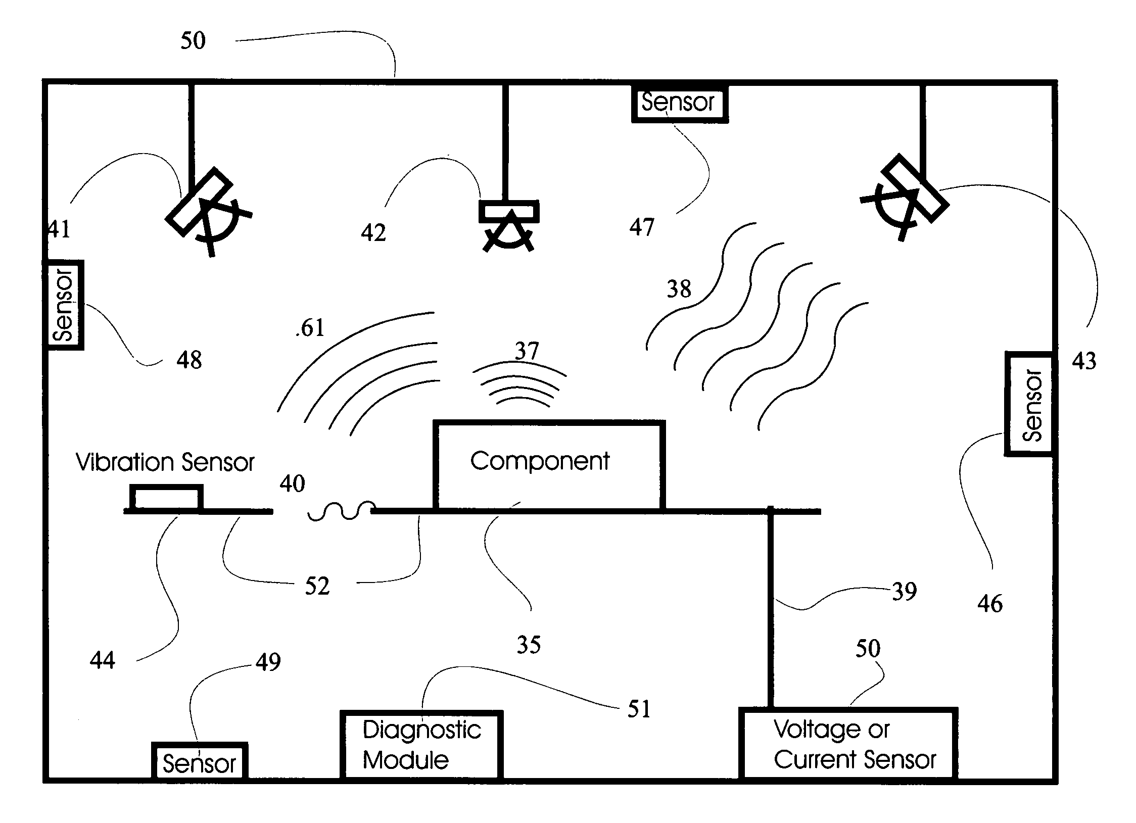
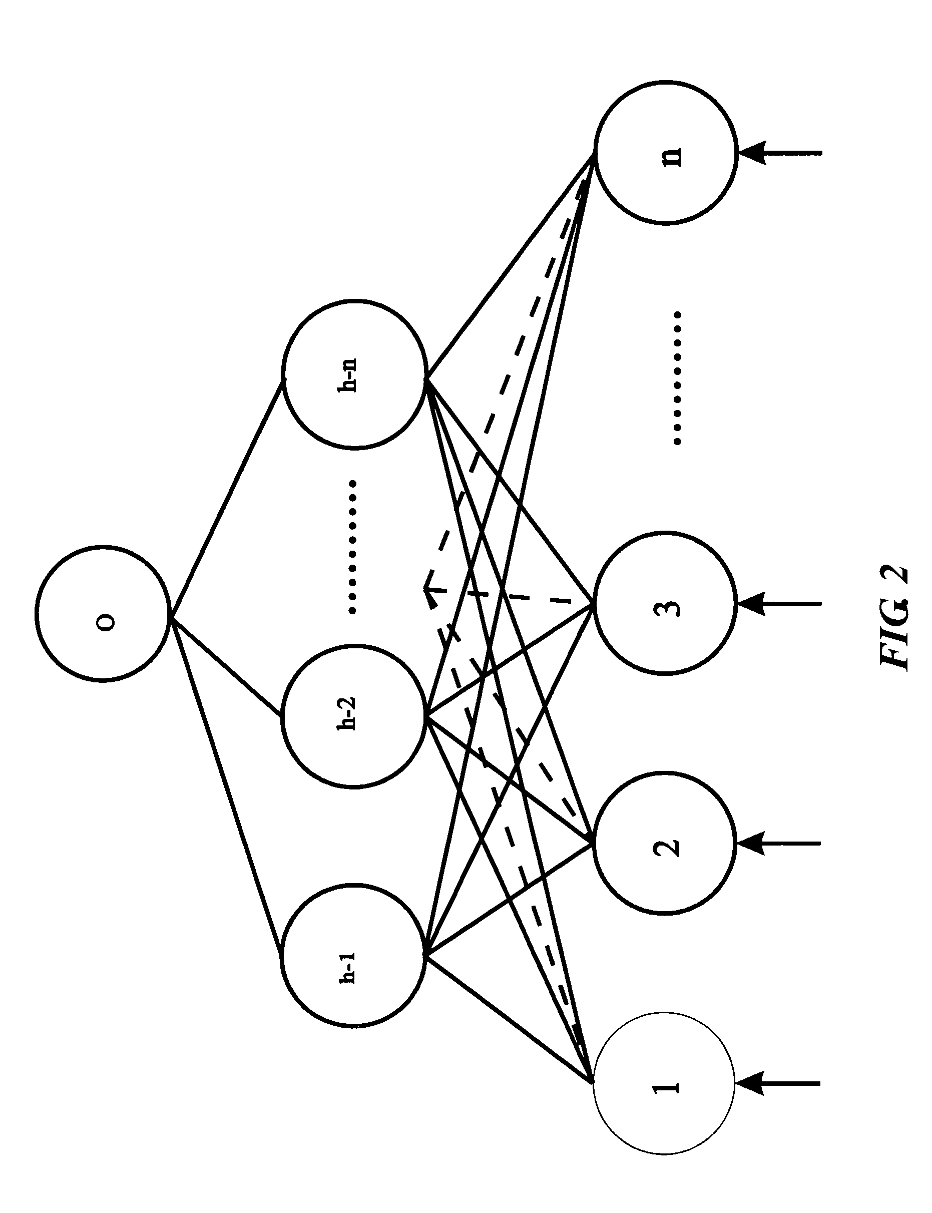
[0144]A preferred embodiment of the vehicle diagnostic unit described below performs the diagnosis, i.e., processes the input from the various sensors, on the vehicle using for example a processor embodying a pattern recognition technique such as a neural network. The processor thus receives data or signals from the sensors and generates an output indicative or representative of the operating conditions of the vehicle or its component. A signal could thus be generated indicative of an under-inflated tire, or an overheating engine.

[0145]For the discussion below, the following terms are defined as follows:

[0146]The term “component” as used herein generally refers to any part or assembly of parts which is mounted to or a part of a motor vehicle and which is capable of emitting a signal representative of its operating state. The following is a partial list of general automobile and truck components, the list not being exhaustive:

[0147]engine;

[0148]transmission;

[01...


PUM


Abstract

Information management and monitoring system for a vehicle including a vehicle monitoring system including a plurality of sensors for monitoring vehicular components, a diagnostic module arranged on the vehicle and coupled to the vehicle monitoring system to receive and process data about the components therefrom, and a remote service center capable of servicing the components. A communication system, e.g., a cellular telephone capable of voice communications, is arranged on the vehicle and coupled to the diagnostic module to enable communications of data from the diagnostic module to the remote service center such that the remote service center receives data about the vehicular components. The remote service center can be situated at a dealer which can have its personnel contact the driver, e.g., via the telephone, to schedule service of the vehicle, the service being determined based on the communicated data from the diagnostic module on the vehicle.

Description

CROSS REFERENCE TO RELATED APPLICATIONS[0001]This application is a divisional of U.S. patent application Ser. No. 10 / 701,361, filed Nov. 4, 2003 which is:[0002]1) a continuation-in-part of U.S. patent application Ser. No. 10 / 188,673 filed Jul. 3, 2002, now U.S. Pat. No. 6,738,697, which is a continuation-in-part of U.S. patent application Ser. No. 09 / 753,186 filed Jan. 2, 2001, now U.S. Pat. No. 6,484,080, which is a continuation-in-part of U.S. patent application Ser. No. 09 / 137,918 filed Aug. 20, 1998, now U.S. Pat. No. 6,175,787, which is a continuation-in-part of U.S. patent application Ser. No. 08 / 476,077 filed Jun. 7, 1995, now U.S. Pat. No. 5,809,437; and[0003]2) a continuation-in-part of U.S. patent application Ser. No. 10 / 174,709 filed Jun. 19, 2002, now U.S. Pat. No. 6,735,506;[0004]3) a continuation-in-part of U.S. patent application Ser. No. 10 / 330,938 filed Dec. 27, 2002, now U.S. Pat. No. 6,823,244;[0005]4) a continuation-in-part of U.S. patent application Ser. No. 10 / ...

Claims


Application Information

Patent Timeline
Patent Type & Authority Patents(United States)
IPC IPC(8): G06F7/00G07C5/00G07C5/08
CPCG07C5/008G07C5/0808B60N2002/0272B60N2/0272
Inventor BREED, DAVID S.
Owner AMERICAN VEHICULAR SCI
Why Eureka
Try Eureka