Non-rotating sensor assembly for measurement-while-drilling applications

a sensor assembly and sensor technology, applied in the field of acquisition and processing of data acquired by a measurementwhiledrilling, can solve the problems of adversely affecting the measurement of nmr, prior art devices are limited to measurement devices,

Inactive Publication Date: 2006-08-01
BAKER HUGHES INC
View PDF20 Cites 33 Cited by
  • Summary
  • Abstract
  • Description
  • Claims
  • Application Information

AI Technical Summary

Benefits of technology

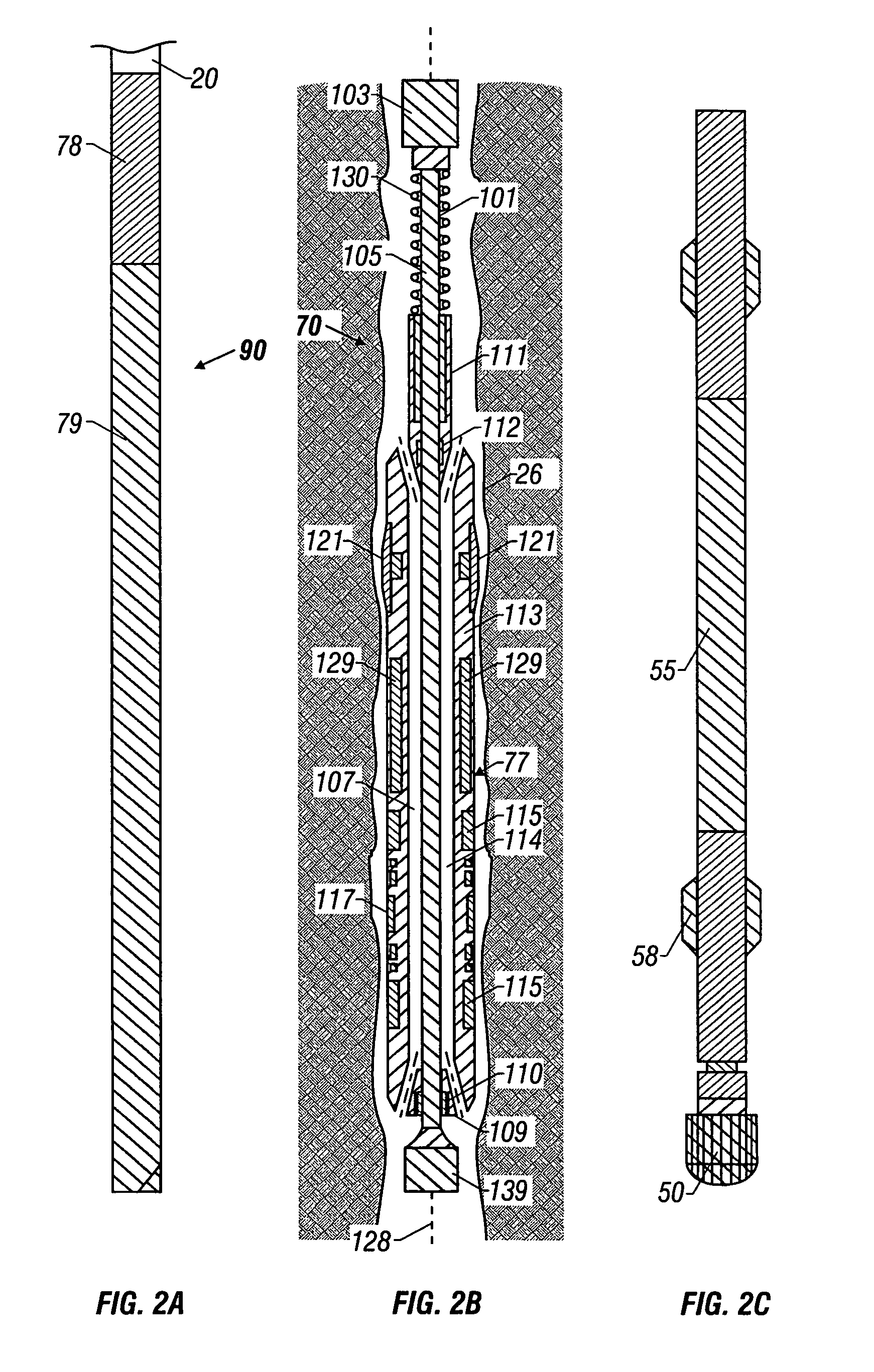
[0005]The present invention is an apparatus and method of determining a parameter of interest of a formation surrounding a borehole while drilling the borehole. In one aspect of the invention, the drill bit is mounted on a rotating drillstring or coiled tubing. The present invention includes a longitudinal member, for example, a segment of drill pipe included in the drillstring and rotating with the drillstring, or a shaft on a downhole directional drilling assembly. A sensor assembly is slidably coupled to the longitudinal member wherein the sensor assembly includes at least one sensor for obtaining measurements relating to the parameter of interest. When the sensor assembly is held in a non-rotating position, for instance, for obtaining the measurements, the longitudinal member is free to rotate and continue drilling the borehole. The sensor assembly is slidably coupled to the longitudinal member using, for example, at least one guide sleeve slidably coupled to the longitudinal member. The sensor assembly further includes, for example, at least one transmitter. The sensor assembly of the present invention can include any of a variety of sensors and / or transmitters for determining a plurality of parameters of interest including, for example, nuclear magnetic resonance measurements.

Problems solved by technology

Prior art devices are limited to measurement devices that rotate with the drillstring.
This is particularly problematic in nuclear magnetic resonance (NMR) measurements where lateral vibrations of a drill collar containing the NMR device would adversely affect an NMR measurement.
Prior art NMR devices in which the static magnetic fields are produced by magnets located in the drilling collar suffer from the additional disadvantage that the resonance region extends into the borehole, as a result of which an electromagnetic signal is produced in the borehole fluid.

Method used


Image

  • Non-rotating sensor assembly for measurement-while-drilling applications
  • Non-rotating sensor assembly for measurement-while-drilling applications
  • Non-rotating sensor assembly for measurement-while-drilling applications

Examples


Embodiment Construction

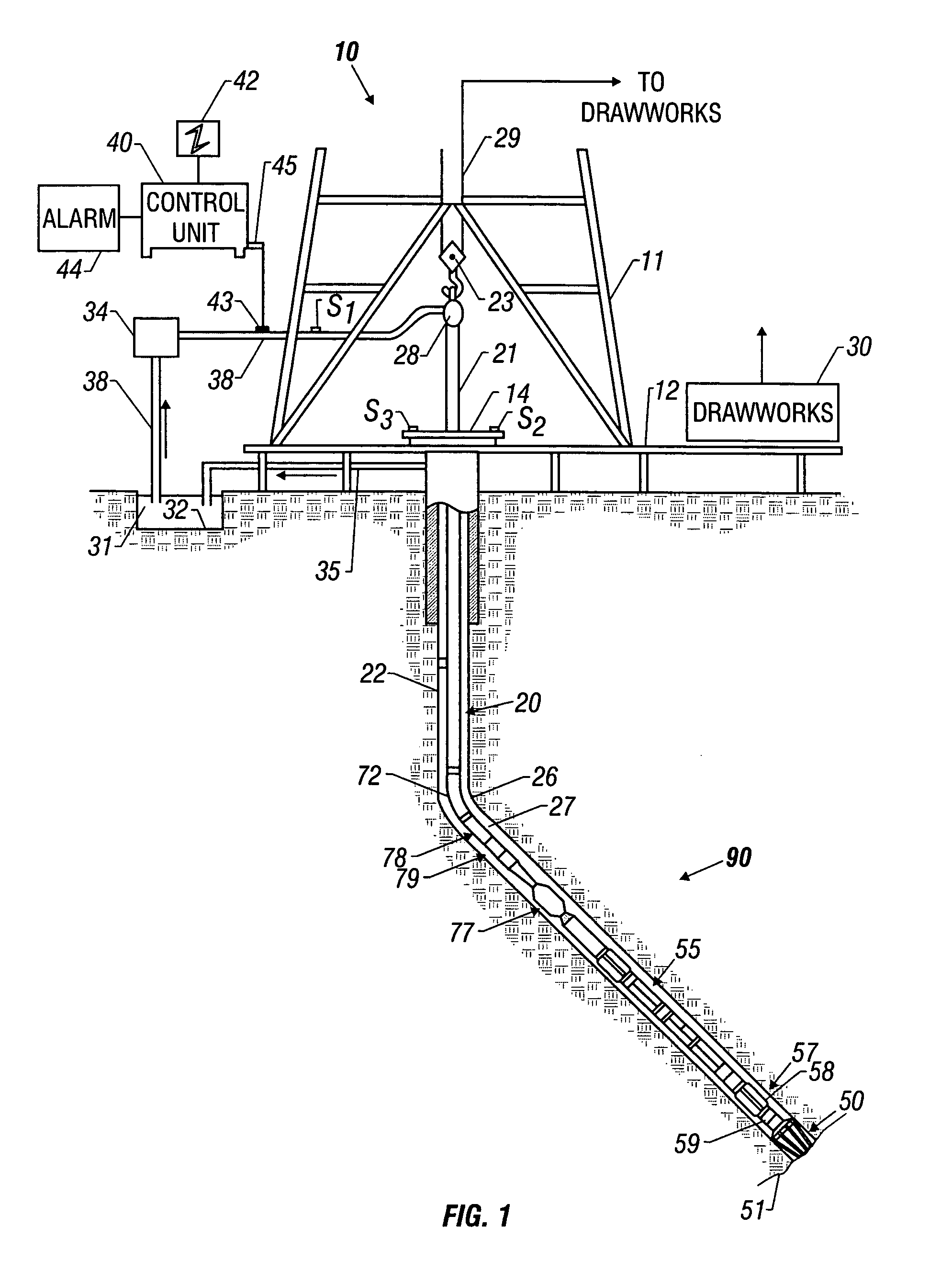
[0027]FIG. 1 shows a schematic diagram of a drilling system 10 with a drillstring 20 carrying a drilling assembly 90 (also referred to as the bottom hole assembly, or “BHA”) conveyed in a “wellbore” or “borehole”26 for drilling the wellbore. The drilling system 10 includes a conventional derrick 11 erected on a floor 12 which supports a rotary table 14 that is rotated by a prime mover such as an electric motor (not shown) at a desired rotational speed. The drillstring 20 includes a tubing such as a drill pipe 22 or a coiled-tubing extending downward from the surface into the borehole 26. The drillstring 20 is pushed into the wellbore 26 when a drill pipe 22 is used as the tubing. For coiled-tubing applications, a tubing injector (not shown) is used to move the tubing from a source thereof, such as a reel (not shown), to the wellbore 26. The drill bit 50 attached to the end of the drillstring breaks up the geological formations when it is rotated to drill the borehole 26. If a drill ...


PUM


Abstract

An MWD method and apparatus for determining parameters of interest in a formation has a sensor assembly mounted on a slidable sleeve slidably coupled to a longitudinal member, such as a section of drill pipe. When the sensor assembly is held in a non-rotating position, for instance for obtaining the measurements, the longitudinal member is free to rotate and continue drilling the borehole, wherein downhole measurements can be obtained with substantially no sensor movement or vibration. This is particularly useful in making NMR measurements due to their susceptibility to errors due caused by tool vibration. In addition, the substantially non-rotating arrangement of sensors makes it possible to efficiently carry out VSPs, reverse VSPs and looking ahead of the drill bit. A clamping device is used, for instance, to hold the sensor assembly is held in the non-rotating position. The sensor assembly of the present invention can include any of a variety of sensors and/or transmitters for determining a plurality of parameters of interest including, for example, nuclear magnetic resonance measurements.

Description

CROSS REFERENCES TO RELATED APPLICATIONS[0001]This application is a Continuation of U.S. patent application Ser. No. 10 / 119,586 filed on Apr. 10, 2002 (now U.S. Pat. No. 6,637,524) which is a Continuation of U.S. patent application Ser. No. 09 / 839,423 filed on Apr. 20, 2001 now U.S. Pat. No.6,446,736 which is a continuation of U.S. patent application Ser. No. 09 / 247,340 filed on Feb. 9, 1999 now U.S. Pat. No. 6,247,542 which claimed priority from Provisional U.S. patent application Ser. No. 60 / 077,144 filed on Mar. 6, 1998.FIELD OF THE INVENTION[0002]This invention relates to the acquisition and processing of data acquired by a measurement-while-drilling (MWD) tool during the drilling of a wellbore. More particularly, the invention relates to methods and devices for acquiring data downhole using a tool that is adapted to be clamped to the borehole wall during drilling operations.BACKGROUND OF THE INVENTION[0003]Modern well drilling techniques, particularly those concerned with the d...

Claims


Application Information

Patent Timeline
Patent Type & Authority Patents(United States)
IPC IPC(8): E21B47/00E21B33/124E21B41/00E21B43/26E21B49/00E21B49/06E21B49/10G01R33/44G01V3/32
CPCE21B33/1243E21B43/26E21B49/008G01V3/32E21B49/10E21B49/06E21B2041/0028E21B2200/22
Inventor KRUSPE, THOMASKRUEGER, VOLKER
Owner BAKER HUGHES INC
Why Eureka
Try Eureka