Double connector for medical sensor

a technology of connectors and medical sensors, applied in the direction of diagnostic recording/measuring, coupling device connections, diagnostics, etc., to achieve the effect of reducing the number of branches and facilitating faster connections

Inactive Publication Date: 2006-08-01
KONINK PHILIPS ELECTRONICS NV
View PDF12 Cites 37 Cited by
  • Summary
  • Abstract
  • Description
  • Claims
  • Application Information

AI Technical Summary

Benefits of technology

[0009]The present invention provides a zero-insertion force (ZIF) connector that easily connects a two-conductor cable to a medical electrode or medical sensor having two connections. According to an aspect of the invention, the medical electrode or sensor can be disposable, and may include a snap stud connection so the connector attaches with Zero insertion force onto a stud. According to an aspect of the invention, the zero insertion force permits the connector to be attached to the electrode or sensor after the electrode has been positioned on the patient without discomfort.
[0010]According to another aspect of the invention, the connector can be polarized to properly attach to the double electrode. The invention also permits the connections to be made faster (only four instead of eight), and reduces the number of branches. In addition, a double connector prevents the substitution of standard (single) ECG electrodes that would introduce variability in the impedance cardiography test results.

Problems solved by technology

However, the use of two connectors for each double electrode still requires eight individual connections to these electrodes.

Method used


Image

  • Double connector for medical sensor
  • Double connector for medical sensor
  • Double connector for medical sensor

Examples


Embodiment Construction

[0016]It is understood by persons of ordinary skill in the art that the illustrations and description herein are provided for purposes of explanation, and the claimed invention is not limited to the embodiments shown and described, as an artisan can make variations in the design that lie within the spirit of the invention and the scope of the appended claims.

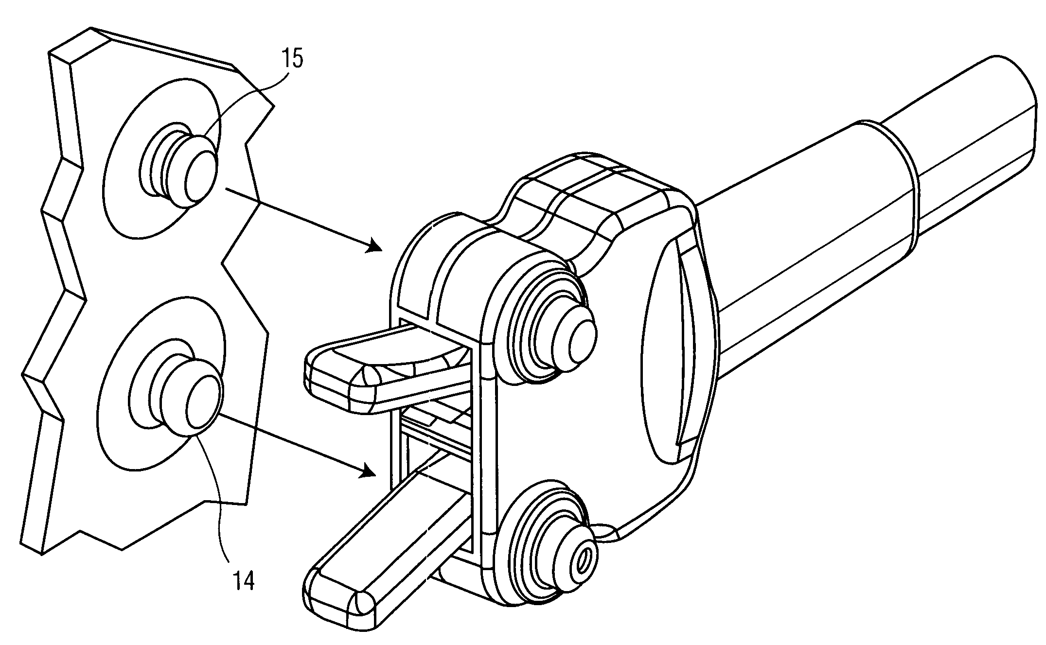
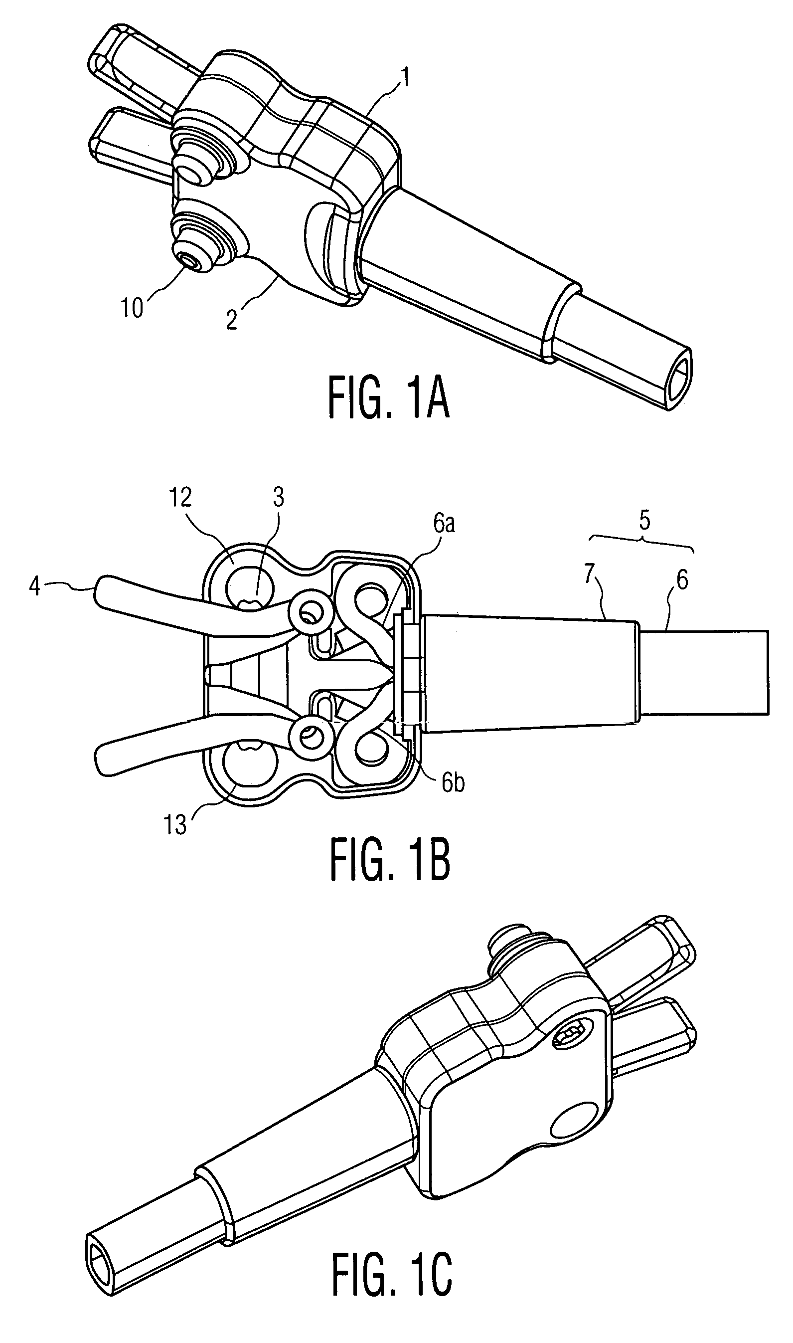
[0017]According to an aspect of the invention shown in FIGS. 1A and 1B, a double connector includes a housing comprising a base 1 and cover 2. The base is preferably constructed of injection-molded plastic, but suitable substitutes can be used. The base has two holes 12, 13 (shown in FIG. 1B), with the smaller hole 12 permitting only a smaller stud of a double sensor (Item 15, FIG. 2) to pass but preventing a larger stud (e.g., item 14, FIG. 2) from entering.

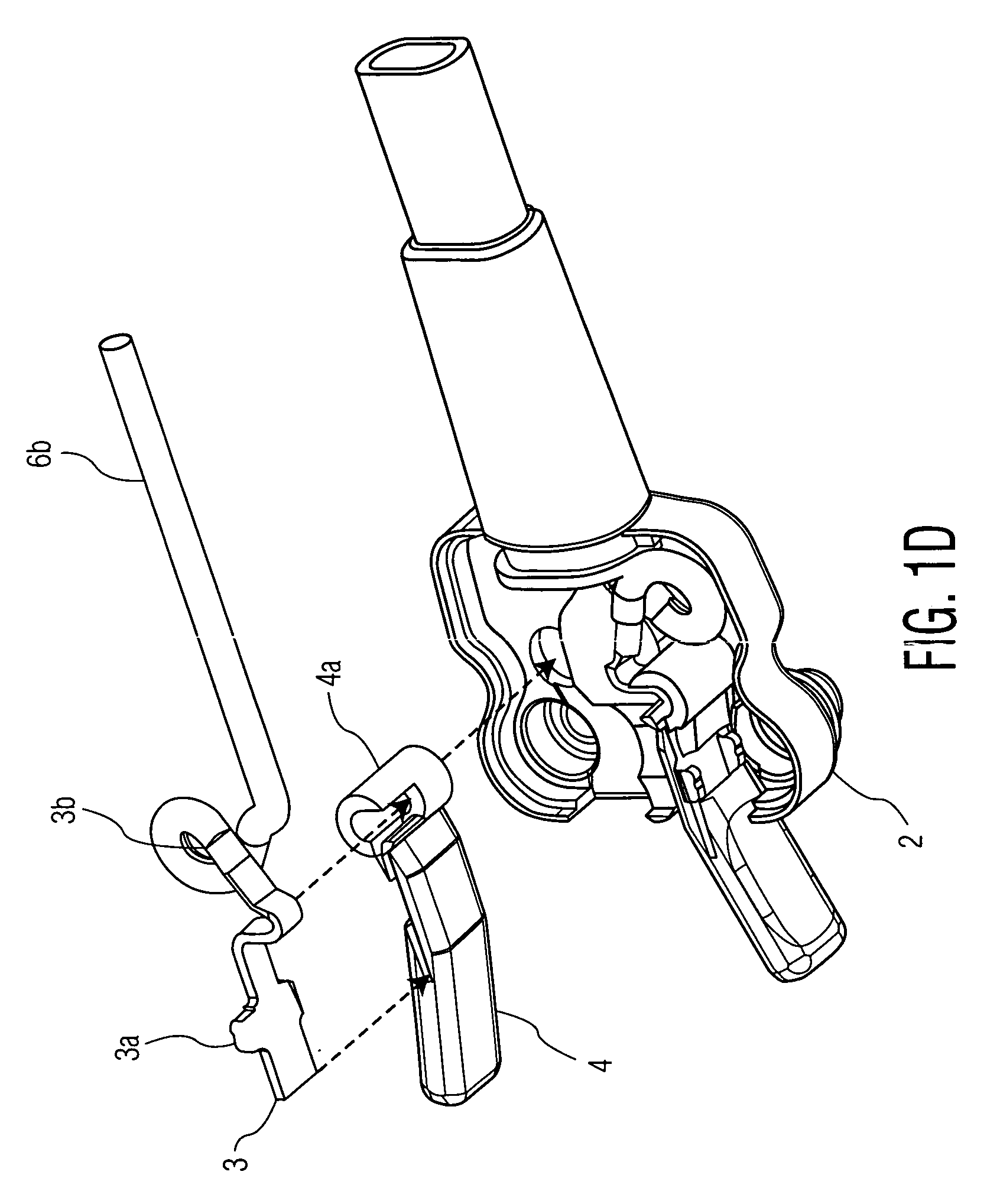
[0018]As best shown in FIG. 1D, there are two electrical contacts 3 which fit into respective recesses of handles 4. In this particular case, the electrical contacts 3 may s...


PUM


Abstract

A double electrode connector for connecting to medical electrodes preferably in an impedance cardiography system includes a connector housing comprising a base having two holes therein of predetermined diameters arranged at predetermined location in the housing, with a first of the two holes associated with a first connector and a second of the two holes associated with a second connector of the double-electrode connector; a pair of biasing elements arranged along a surface of the housing so that each one of the pair of biasing elements is adapted for biasing against an electrode stud inserted in a respective hole of the two holes in the housing; a cable assembly including a twin wire cable and a bend relief, wherein each one of the pair of metal lugs is connected to one of the first connector and second connector, and the bend relief is arranged in a hole in the base to flexibly connect the twin wire cable to respective metal lugs of the pair of metal lugs. The biasing means may include handles to assist with attaching the double connector to two electrodes with a near-zero insertion force towards a patient.

Description

CROSS REFERENCE TO RELATED APPLICATION[0001]This application claims the benefit of U.S. provisional application Ser. No. 60 / 435,246 filed Dec. 20, 2002, which is incorporated herein by reference.BACKGROUND OF THE INVENTION[0002]1. Field of Invention[0003]The present invention relates to improved electrical clasp structures for transferring electrical signals to a medical electrode. More particularly, the present invention relates to a double connector for impedance cardiography.[0004]2. Description of the Related Art[0005]Impedance cardiography (ICG) is a medical test to determine the pumping capacity of the heart. ICG is a non-invasive and cost-effective technique for determining stroke volume (SV), cardiac output (CO), and thoracic fluid volume (TFC, or ZO). Impedance cardiography is also referred to as “Non-Invasive Continuous Cardiac Output” (NiCCO), which requires four pairs of electrodes to perform the testing.[0006]In prior art systems, such as, for example the IQ System (Wan...

Claims


Application Information

Patent Timeline
Patent Type & Authority Patents(United States)
IPC IPC(8): H01R4/48H01R33/08A61B5/274H01R11/22
CPCA61B5/04085A61B5/0416A61B5/6843H01R4/4836H01R13/193H01R13/6275H01R13/6277H01R11/22H01R2201/12A61B5/274A61B5/282H01R4/48365
Inventor SILBER, DANIEL A.
Owner KONINK PHILIPS ELECTRONICS NV
Why Eureka
Try Eureka