Organic electroluminescent device and method for fabricating same

a technology of electroluminescent devices and organic el, which is applied in the direction of discharge tube luminescnet screens, natural mineral layered products, transportation and packaging, etc., can solve the problems of insufficient elimination of ingress of moisture from the interface between the above layers, poor moisture resistance, and affect the organic el device. , to achieve the effect of generating less number of dark spots and excellent long-term moisture resistan

Inactive Publication Date: 2006-08-01
SAMSUNG DISPLAY CO LTD
View PDF17 Cites 12 Cited by
  • Summary
  • Abstract
  • Description
  • Claims
  • Application Information

AI Technical Summary

Benefits of technology

[0010]In view of the foregoing, an object of the present invention is to provide an organic EL device having an excellent long-term moisture resistance and generating less number of dark spots, by using various desiccants in a sufficient amount.

Problems solved by technology

However, such an organic EL device is affected by surrounding moisture and has a poor moisture resistance.
However, in the organic EL device described therein, the ingress of the moisture from the interfaces between the organic EL device and the above layers cannot be sufficiently eliminated.
Further, the stress caused by the formation of these layers reduces the luminescent efficiency of the organic EL device or destroys the organic EL device depending on circumstances.
Since, however, the moisture absorption by the porous layer utilizes only physical adsorption, the influence of the moisture cannot be sufficiently eliminated.
In addition, since the surface area of the porous layer is reduced by the inner wall area of the sealing glass, the elimination of the moisture influence for a longer period of time is difficult.
Since, however, the amount of the desiccant which can be fixed by the adhesive is restricted by the surface area of the inner wall of the sealing can, the smaller amount of the desiccant cannot effectively eliminate moisture influence for a longer period of time.
In addition, since the employable desiccants are limited to one that maintains the solid state even after absorbing moisture, use of a hygroscopic desiccant or a deliquescent desiccant is difficult.

Method used


Image

  • Organic electroluminescent device and method for fabricating same
  • Organic electroluminescent device and method for fabricating same
  • Organic electroluminescent device and method for fabricating same

Examples


first embodiment

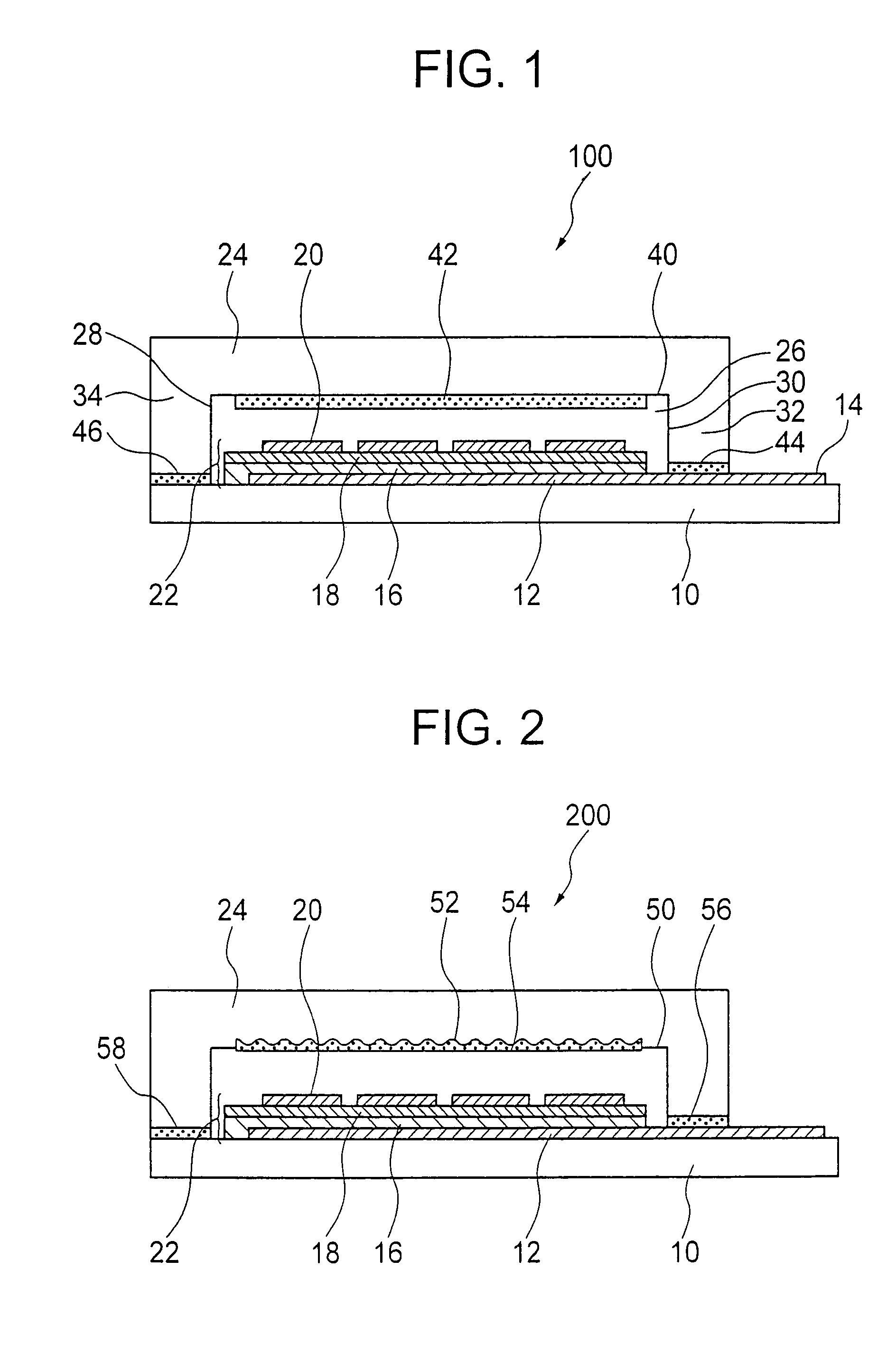
[0021]An organic EL device 100 of a first embodiment shown in FIG. 1 includes an EL stacked structure 22, or an organic EL thin film layers, including an organic luminescent layer 18 and a hole transport layer 16 sandwiched between an anode 12 and a cathode 20. The stacked structure 22 is sealed between a transparent substrate 10 and a sealing can 24. The organic EL device 100 has a desiccant-containing layer 42 formed on the inner surface 40 of the sealing can 24.

(1) Transparent Substrate

[0022]The transparent substrate used in the first embodiment is not especially restricted so long as the transparent substrate supports the stacked structure, allows external emission of light from the stacked structure and shields the interior of the organic EL device from the atmosphere. The transparent substrate is preferably a glass substrate or a transparent polymer substrate because of their excellent light transmittance and the stability and the durability of the resulting organic EL device....

second embodiment

[0045]A second embodiment shown in FIG. 2 is a modified example of the first embodiment. An organic EL device 200 of the second embodiment includes the stacked structure 22 formed by the organic luminescent layer 18 and the hole transport layer 16 positioned between the anode 12 and the cathode 20. The stacked structure 22 is sealed between the transparent substrate 10 and the sealing can 24. A concave-convex surface 52 is formed on the inner surface 50 of the sealing can 24, and another desiccant-containing layer 54 is formed on the concave-convex surface 52.

[0046]The concave-convex surface 52 has an anchoring effect for firmly fixing the desiccant-containing layer to the inner surface of the sealing can. The desiccant-containing layer 54 easily changes its shape in accordance with the concave-convex surface 52 to increase its surface area resulting in elevation of the moisture absorbing ability.

[0047]Although the shape of the concave-convex surface 52 is not especially restricted ...

third embodiment

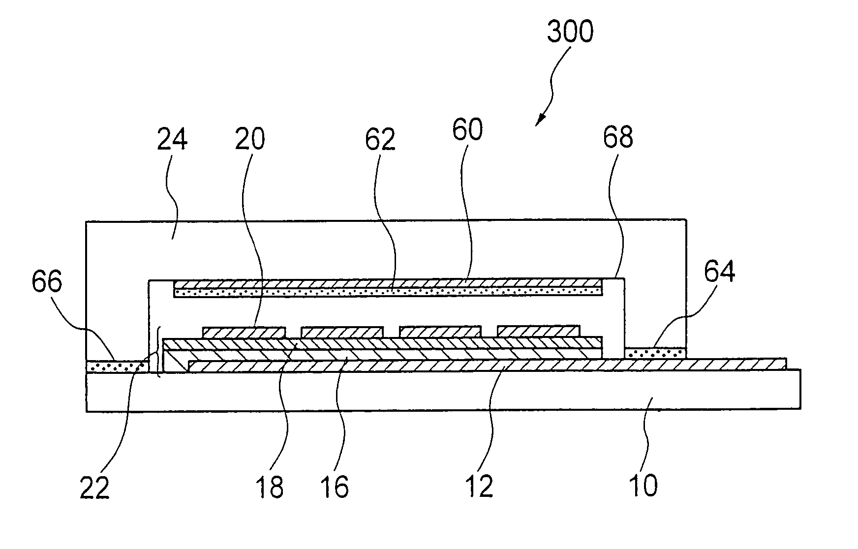
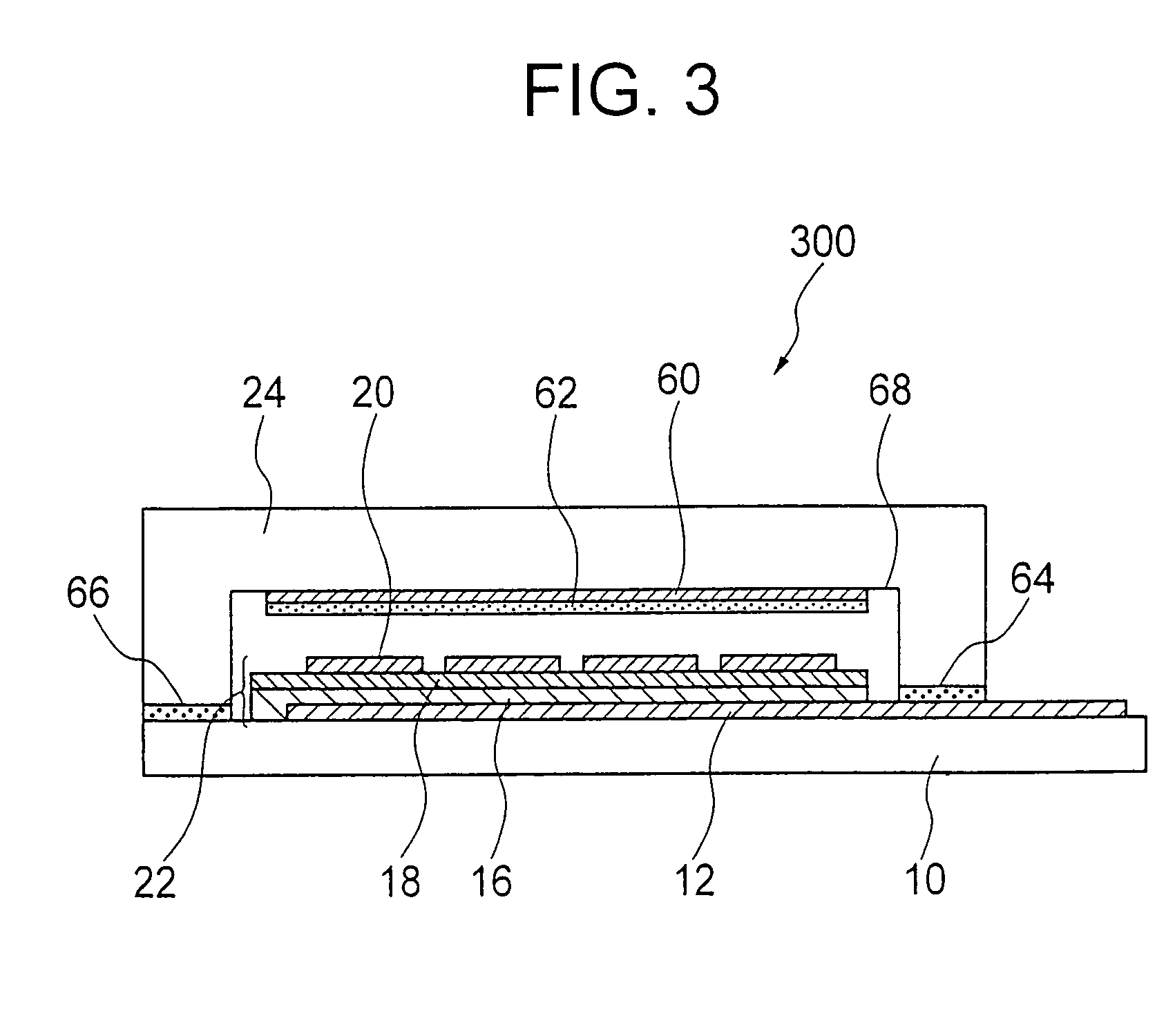
[0050]A third embodiment shown in FIG. 3 is a modified example of the first embodiment. An organic EL device 300 of the third embodiment includes the stacked structure 22 formed by the organic luminescent layer 18 and the hole transport layer 16 positioned between the anode 12 and the cathode 20. The stacked structure 22 is sealed between the transparent substrate 10 and the sealing can 24. A desiccant-containing layer 62 is layered on the inner surface 68 of the sealing can 24 by using an adhesive 60.

[0051]The use of the desiccant-containing layer 62 in the form of a sheet enables the elevation of the effect of the fabricating step, or the attainment of the low-cost fabrication because a significant number of the desiccant-containing layers can be prepared at a time.

[0052]The desiccant-containing layer 62 and the adhesive 60 in the third embodiment will be described.

(1) Desiccant-Containing Layer

[0053]The desiccant-containing layer 62 used in the -third embodiment has the functions...


PUM

PropertyMeasurementUnit
thicknessaaaaaaaaaa
thicknessaaaaaaaaaa
particle sizeaaaaaaaaaa

Abstract

An organic EL device including a stacked structure having an organic luminescent layer positioned between an anode and a cathode; and a sealing can having a desiccant-containing layer on its inner surface. The desiccant in the desiccant-containing layer provides an excellent long-term moisture resistance to the organic EL device, thereby generating no or a few dark spots thereon.

Description

CROSS REFERENCE[0001]This application is a continuation application of Applicant's U.S. patent application Ser. No. 09 / 614,874 filed on Jul. 12, 2000, that issued as U.S. Pat. No. 6,737,176.BACKGROUND OF THE INVENTION[0002](a) Field of the Invention[0003]The present invention relates an organic electroluminescent (hereinafter referred to as “EL”) device having an excellent long-term moisture resistance, and a method for fabricating the same.[0004](b) Description of the Related Art[0005]In a field of a flat display device, an organic EL device including an organic luminescent layer between an anode and a cathode has been conventionally proposed, and researches therefor are actively conducted. However, such an organic EL device is affected by surrounding moisture and has a poor moisture resistance. Ingress of water contents to the interface between the organic luminescent layer and the electrode prevents injection of electrons, thereby generating dark spots showing a non-luminescent r...

Claims


Application Information

Patent Timeline
Patent Type & Authority Patents(United States)
IPC IPC(8): H05B33/12H01L27/32H01L51/50H01L51/52H01L51/54H01L31/12H05B33/04H05B33/10H05B33/14
CPCH01L51/5237H05B33/04Y10T428/23Y10S428/917H10K50/841H10K50/846H01L31/12
Inventor OTSUKI, SHIGEYOSHIFUKUZAWA, SHINICHI
Owner SAMSUNG DISPLAY CO LTD
Why Eureka
Try Eureka