Electro-optic device comprising a recess/projection pattern obtained by rotating a reference pattern about a predetermined position

Active Publication Date: 2006-08-01
BOE TECH GRP CO LTD
View PDF24 Cites 8 Cited by
  • Summary
  • Abstract
  • Description
  • Claims
  • Application Information

AI Technical Summary

Benefits of technology

[0009]In view of the problems mentioned above, an object of the present invention is to provide an electro-optic device capable of reducing or preventing an interference of reflected lig

Problems solved by technology

However, if the recess/projection pattern 8g on the surface of the light reflecting film 8a has the same sloped shape for each pixel 100a, a problem occurs in that reflected lights from the light reflecting film 8a interfere with each other and display quality is noticeably reduced.
Howev

Method used


Image

  • Electro-optic device comprising a recess/projection pattern obtained by rotating a reference pattern about a predetermined position
  • Electro-optic device comprising a recess/projection pattern obtained by rotating a reference pattern about a predetermined position
  • Electro-optic device comprising a recess/projection pattern obtained by rotating a reference pattern about a predetermined position

Examples


Embodiment Construction

[0056]An exemplary embodiment of the present invention will be described below with reference to the drawings.

[0057]Basic Construction of Electro-Optic Device

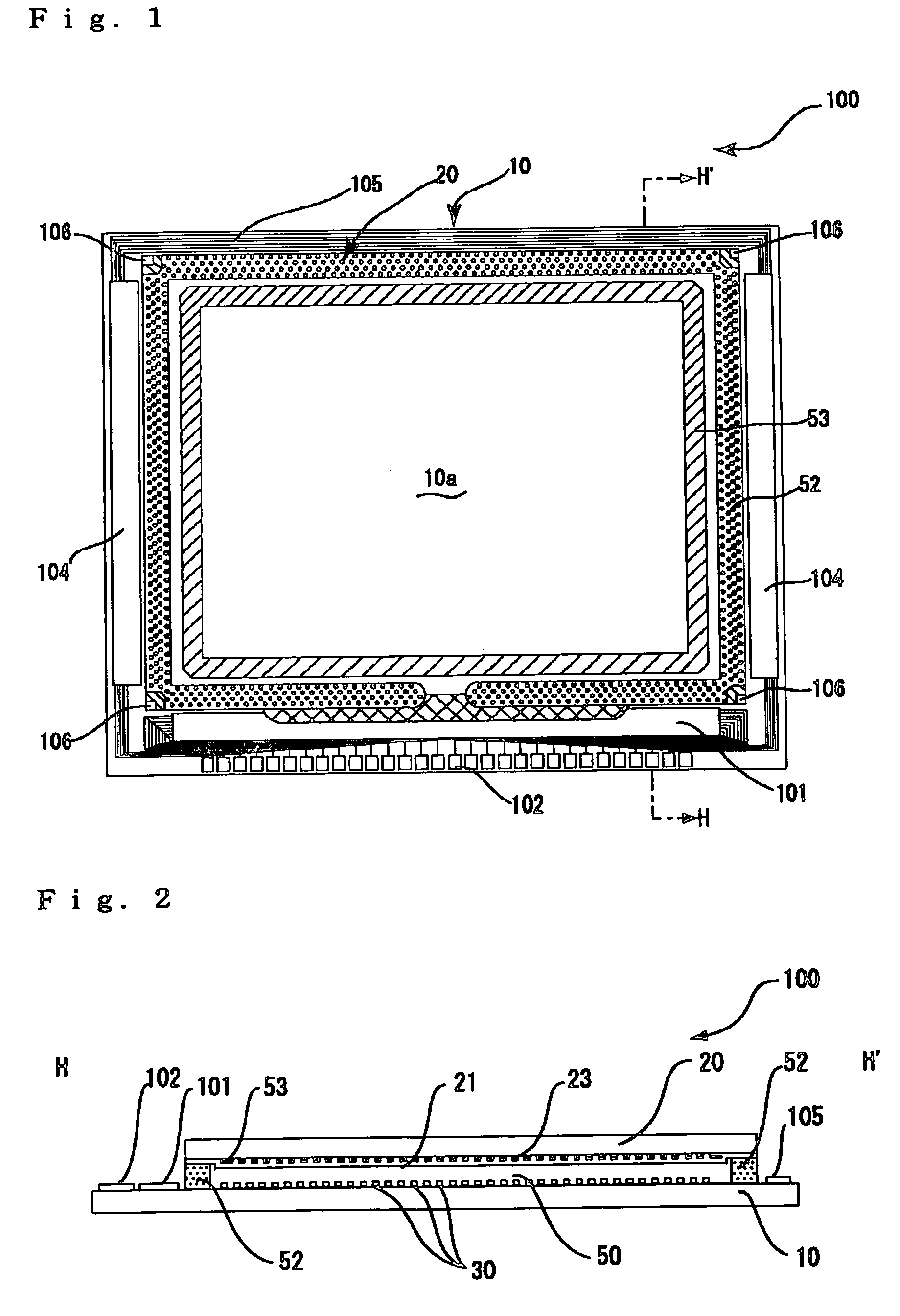
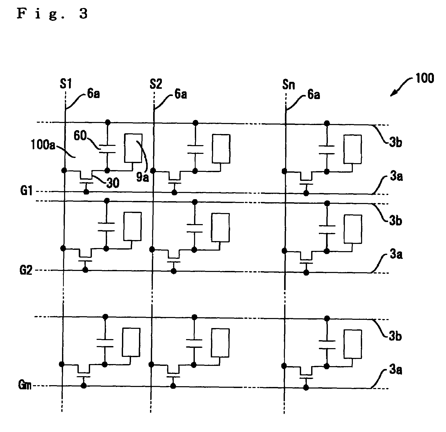
[0058]FIG. 1 is a plan view of an electro-optic device including various components, to which the present invention is applied, looking from the opposed substrate side. FIG. 2 is a sectional view taken along the plane H-H′ in FIG. 1. FIG. 3 is an equivalent circuit schematic of various elements, wiring, etc., which constitute a plurality of pixels formed in a matrix pattern in an image display area of the electro-optic device. In each of the drawings attached for explaining the exemplary embodiment, various layers and various members are shown at different scales so that the various layers and the various members appearing in the drawings large are recognizable.

[0059]Referring to FIGS. 1 and 2, an electro-optic device 100 (liquid crystal device) of this exemplary embodiment includes a TFT array substrate 10 (first substrate) an...


PUM


Abstract

An electro-optic device is provided that is capable of preventing an interference of reflected lights from a light reflecting film and avoiding the occurrence of glare and chrominance non-uniformity among pixels, and an electronic apparatus using the electro-optic device. In a TFT array substrate of a reflective or transflective electro-optic device, a lower-side recess/projection forming film 13a, is formed in each of pixels 100a in the form of a matrix pattern so that a recess/projection pattern to scatter light is formed on the surface of a light reflecting film. The pixels are grouped into a plurality of units, each including a plurality of pixels, and the recess/projection pattern is formed to provide a different pattern for each pixel at least in each of the units. Different recess/projection patterns are obtained, for example, by rotating the recess/projection pattern for a pixel as a reference.

Description

BACKGROUND OF THE INVENTION[0001]1. Field of Invention[0002]The present invention relates to an electro-optic device in which an electro-optic material is held on a substrate, and an electronic apparatus using the electro-optic device. More particularly, the present invention relates to a recess / projection forming technique to form a light-scattering reflecting surface on the substrate used in an electro-optic device.[0003]2. Description of Related Art[0004]Electro-optic devices, such as liquid crystal devices, are employed as direct-view-type displays in various types of equipment. Of those electro-optic devices, a reflective or transflective liquid crystal device employing a TFT active matrix is constructed as shown in FIGS. 20 and 21. In each of multiplicity of pixels 100a arranged in a matrix pattern on the surface of a TFT array substrate 10, a light reflecting film 8a to reflect an extraneous light, which has entered from the opposed substrate side, in a direction toward an op...

Claims


Application Information

Patent Timeline
IPC IPC(8): G02F1/1343G02F1/1335H01L21/77H01L21/84H01L27/12
CPCG02F1/133553H01L27/1214G02F1/1335
Inventor NIMURA, TORUFUJITA, SHIN
Owner BOE TECH GRP CO LTD
Why Eureka
Try Eureka