Electron emitter assembly and method for adjusting a power level of electron beams

a technology of electron beam and power level, which is applied in the field of computed tomography (ct) imaging, can solve the problem that systems cannot adjust the power level of electron beam over a relatively large amount of tim

Active Publication Date: 2006-08-01
GENERAL ELECTRIC CO
View PDF7 Cites 16 Cited by
  • Summary
  • Abstract
  • Description
  • Claims
  • Application Information

AI Technical Summary

Problems solved by technology

A disadvantage of the current CT imaging systems is that the systems can only adjust the power level of an electron beam over a relatively large amount of time by adjusting a high voltage level between an electron emitter device and an anode.

Method used


Image

  • Electron emitter assembly and method for adjusting a power level of electron beams
  • Electron emitter assembly and method for adjusting a power level of electron beams
  • Electron emitter assembly and method for adjusting a power level of electron beams

Examples


Embodiment Construction

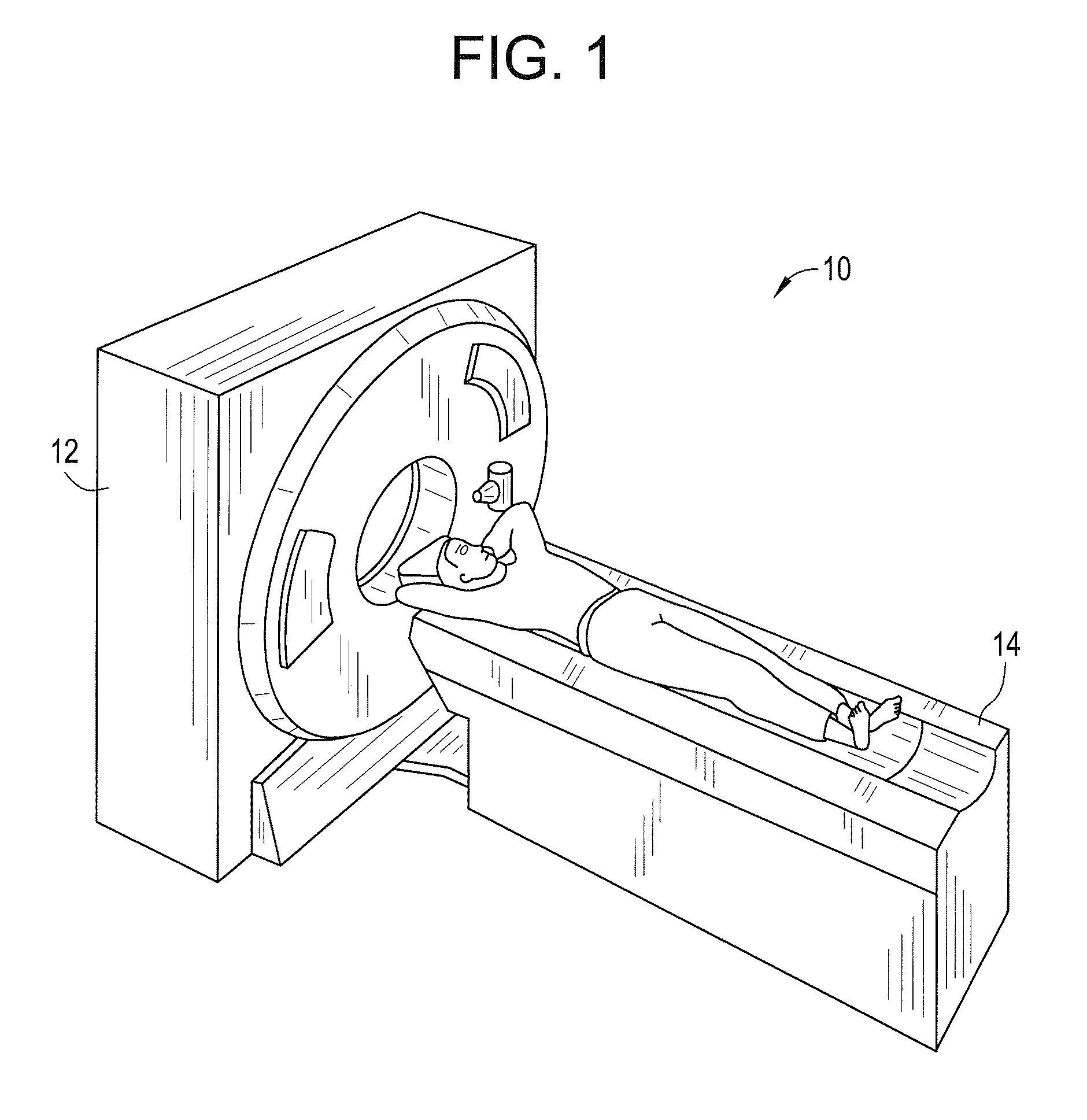
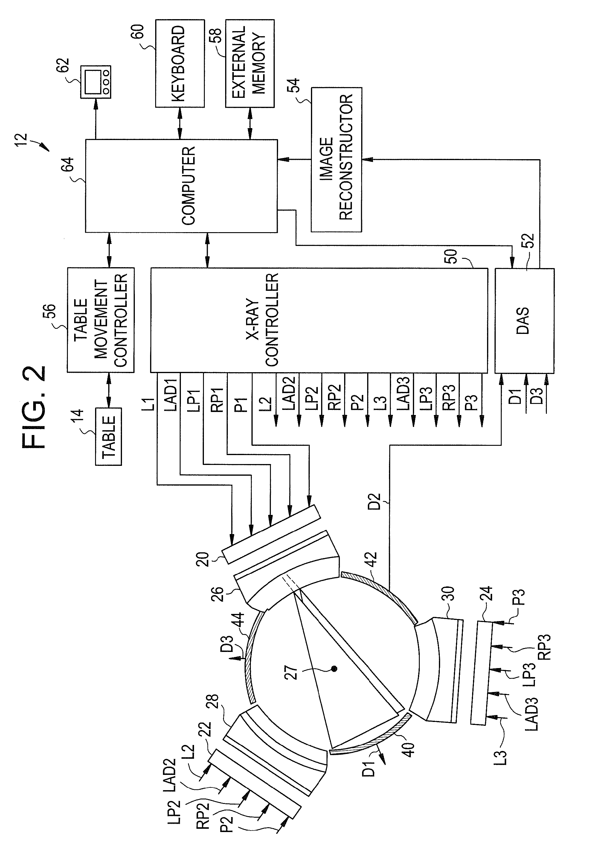
[0022]Referring to FIGS. 1 and 2, a CT imaging system 10 for generating digital images of a target object in accordance with an exemplary embodiment is shown. The CT imaging system 10 includes a CT scanning device 12 and a table 14.

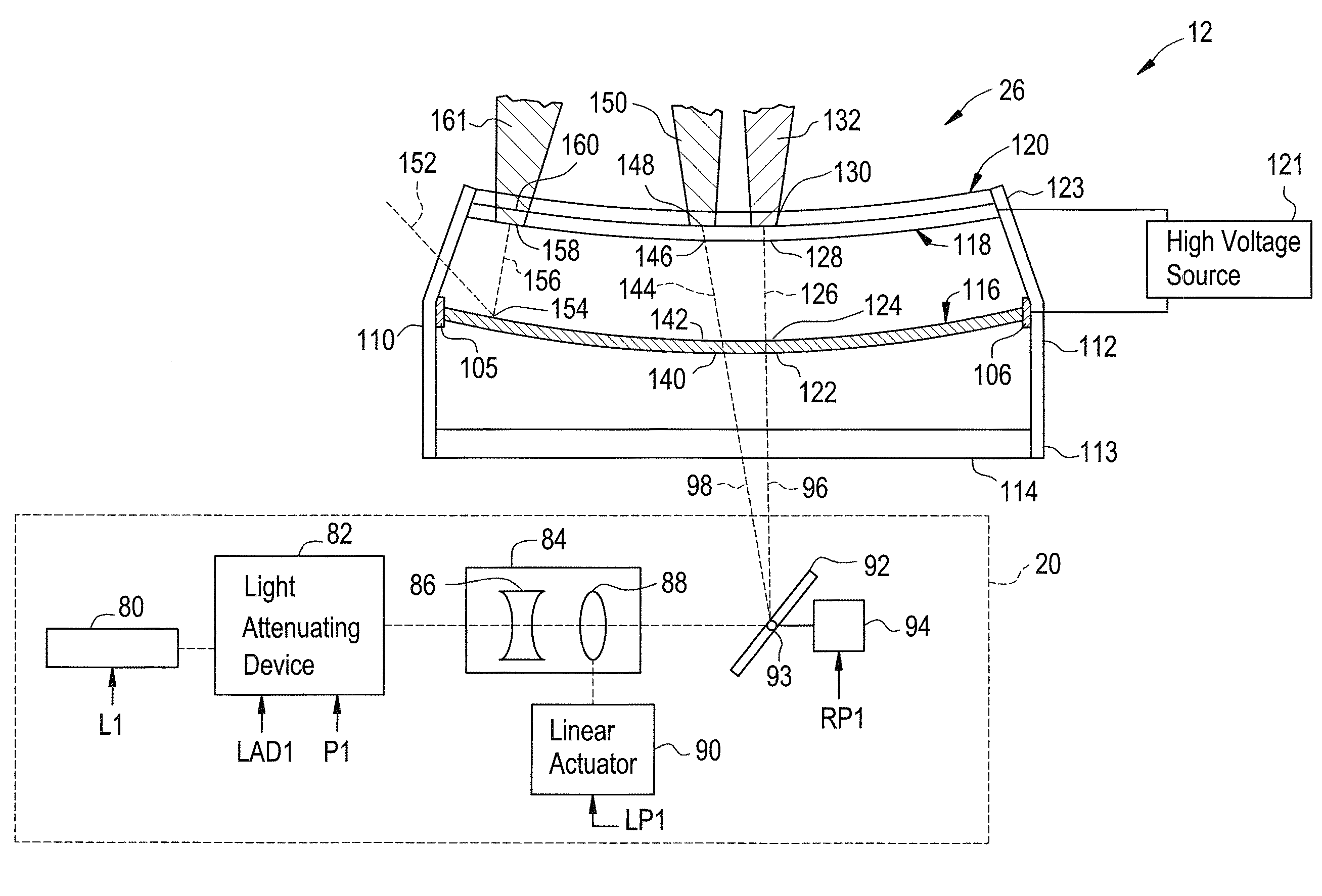
[0023]The CT scanning device 12 is provided to generate a plurality of digital images of a target object. The CT scanning device 12 includes light emitting assemblies 20, 22, 24, x-ray source assemblies 26, 28, 30, x-ray detector arrays 40, 42, 44, an x-ray controller 50, a data acquisition system 52, an image reconstructor device 54, a table movement controller 56, an external memory 58, a keyboard 60, a display monitor 62, and a computer 64. It should be noted that in an alternate embodiment, CT scanning device 12 can have more than or less than three x-ray source assemblies. Further, CT scanning device 12 can have more than or less than three x-ray detector arrays.

[0024]The light emitting assemblies 20, 22, 24 are provided to emit light beams that indu...


PUM


Abstract

An electron emitter assembly and a method for adjusting a power level of an electron beam are provided. The electron emitter assembly includes a laser configured to emit a first light beam. The electron emitter assembly further includes a light-attenuating device configured to receive the first light beam and to attenuate the first light beam between a first light intensity and a second light intensity greater than the first light intensity. The electron emitter assembly further includes a photo-cathode configured to receive the first light beam from the light-attenuating device. The photo-cathode is further configured to emit a first electron beam having a first power level in response to receiving the first light beam having the first light intensity. The photo-cathode is further configured to emit a second electron beam having a second power level greater than the first power level in response to receiving the first light beam having the second light intensity. The electron emitter assembly further includes an anode configured to receive the first and second electrons beams from the photo-cathode.

Description

BACKGROUND OF THE INVENTION[0001]In computed tomography (CT) imaging systems, an x-ray source device and a detector array have been utilized to generate images of an object. The x-ray source device includes an electron emitter device that emits an electron beam that contacts a substrate that emits an x-ray beam in response to the electron beam.[0002]The internal anatomy of a person has different densities in different areas of the body. In relatively high-density areas of the internal anatomy, it is advantageous to increase a power level of x-ray beams so that the x-ray beams can pass through the high-density areas. Further, in relatively low-density areas of the internal anatomy, it is advantageous to decrease a power level of x-ray beams.[0003]A disadvantage of the current CT imaging systems is that the systems can only adjust the power level of an electron beam over a relatively large amount of time by adjusting a high voltage level between an electron emitter device and an anode...

Claims


Application Information

Patent Timeline
Patent Type & Authority Patents(United States)
IPC IPC(8): H01J35/00
CPCH01J35/065H01J35/24H01J2235/087H01J2235/068H01J2235/062H01J35/116
Inventor DUNHAM, BRUCE MATTHEWPRICE, JOHN SCOTTWILSON, COLIN R.
Owner GENERAL ELECTRIC CO
Why Eureka
Try Eureka