Ringback detection circuit

Inactive Publication Date: 2006-08-01
ERICSSON INC
View PDF11 Cites 24 Cited by
  • Summary
  • Abstract
  • Description
  • Claims
  • Application Information

AI Technical Summary

Benefits of technology

[0010]The present invention is a ringback detection circuit for a communication terminal. Ringback detection is based on a comparison of the energy of a received signal to a threshold. The threshold is initialized to 0 or some other low value at the beginning of a call. The threshold is increased based on the energy of the received signal. Ringback is determined to exist when the energy of the received signal equals or exceeds the threshold. Since the threshold is initially set to a low value, the present invention achieves fast detection of ringback. The energy level of the received signal will decrease when ringback ends. It is to be noted that when the energy begins decreasing, the threshold is not updated but instead remains at the current level immediately preceding the decrease in energy. Eventually, the energy of the received signals drops below the threshold indicating that ringback is no longer present.
[0011]The output of the ringback detection circuit is

Problems solved by technology

The wide variety in the composition of ringback tones makes the task of detecting ringback more difficult.
If not detected, ringback may cause problems for adaptive algorithms, such as a voice activity detector (VAD), noise suppressor, acoustic echo canceller (AEC), network echo canceller (NEC), noise estimator, and channel gain estimator.
If the voice activity detector mistakes ringback for noise, this mistake will cause the noise suppressor to train, also by mistake, on ringback.
When voice follows ringback, the voice activity detector may not detect such voice because its internal noise threshold is too high.
Ringback can also cause false training in the acoustic echo canceller and network echo canceller.
False training occurs when the acoustic echo canceller and network echo canceller diverge due to ambiguity caused by the cross correlation between the two inputs being high at multiples of the period of the ringback.
Another problem with ringback occurs in phones with noise estimators.
Ringback may cause the noise estimator to generate a high estimate of noise because the ringback has high amplitude and continues for several seconds.
Since the noise estimate is used by the comfort noise generator, the comfort noise may be initially high and decay when ringback ends.
This can be an annoyance to th

Method used


Image

  • Ringback detection circuit
  • Ringback detection circuit
  • Ringback detection circuit

Examples


Example

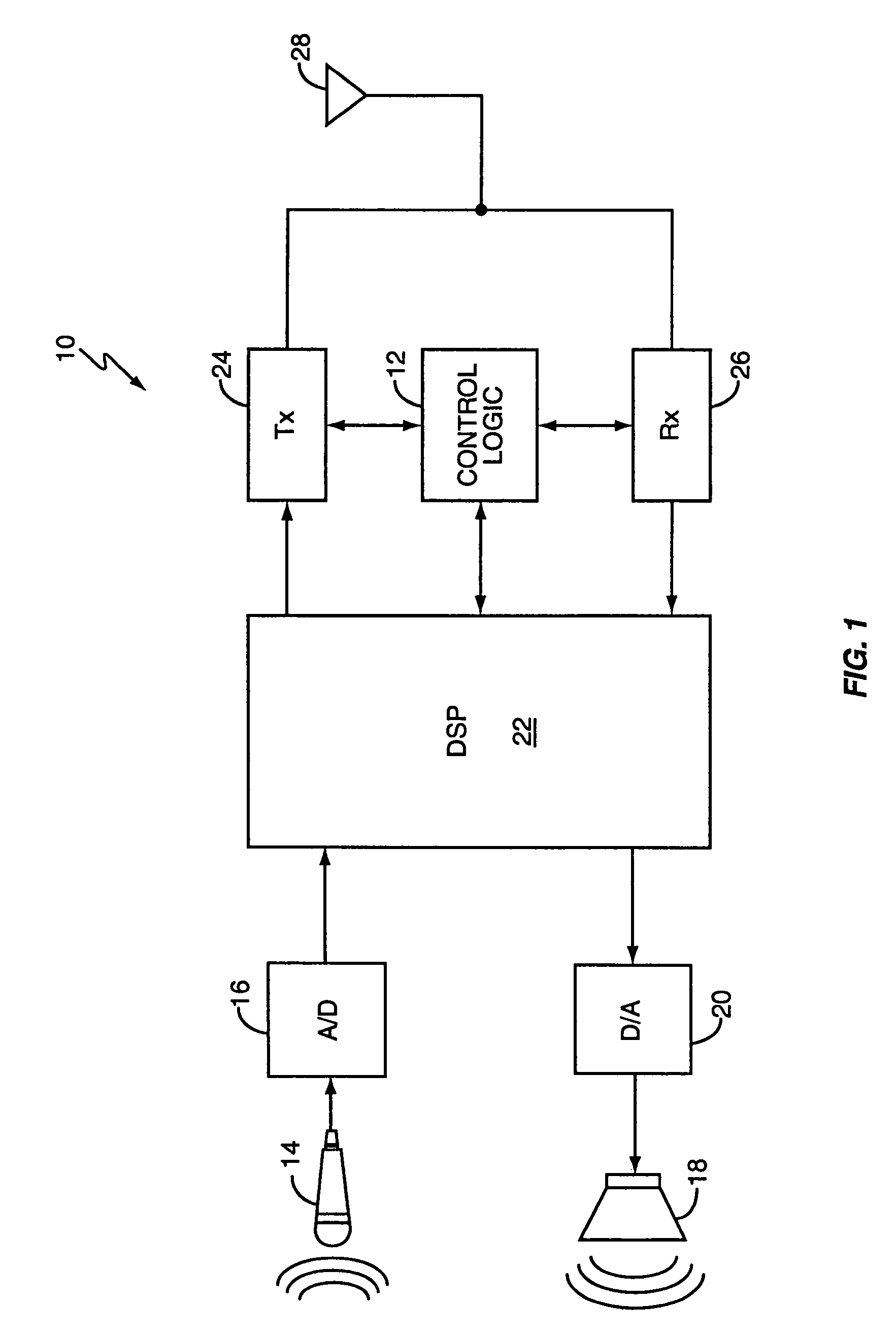
[0020]FIG. 1 is a functional block diagram of an exemplary mobile terminal 10 with a ringback detection circuit 100. Mobile terminal 10 includes control logic 12, microphone 14, analog-to-digital converter 16, speaker 18, digital-to-analog converter 20, digital signal processor 22, transmitter 24, receiver 26, and antenna 28. Control logic 12 controls the operation of the mobile terminal 10 according to stored program instructions. These program instructions can be stored in internal memory within the control logic 12 or in an external memory (not shown). Control logic 12 may be implemented in a single microprocessor or in multiple processors. In the transmit chain, microphone 14 receives acoustic signals from the user and converts the acoustic signals to analog, electrical signals. The analog signals from microphone 14 are converted to digital signals by analog-to-digital converter 16. The digital signals output by the analog-to-digital converter 16 are passed to the digital signal...


PUM


Abstract

A ringback detector determines whether ringback by comparing measurements of a characteristic of the received signal, such as the energy of the received signal, to a threshold. The threshold is set initially to a low value and then updated based on the measurements of received signal. The measurements are then compared to the threshold to determine whether ringback is present. An output signal indicative of ringback is generated when ringback is present.

Description

BACKGROUND OF THE INVENTION[0001]The present invention relates generally to ringback detection circuits for communication terminals and, more particularly, to an adaptive ringback detection circuit that dynamically updates thresholds used for ringback detection.[0002]Ringback is a tone heard by the user of a communication terminal that initiates a call until the call connects. Typically, the ringback is composed of two or more different tones, but single tone ringbacks are known. There is no standard for ringback frequency and cadences. For example, a typical PBX can be configured to generate different tones and cadences according to customer preferences. The wide variety in the composition of ringback tones makes the task of detecting ringback more difficult.[0003]If not detected, ringback may cause problems for adaptive algorithms, such as a voice activity detector (VAD), noise suppressor, acoustic echo canceller (AEC), network echo canceller (NEC), noise estimator, and channel ga...

Claims


Application Information

Patent Timeline
IPC IPC(8): H04M1/00G10L11/02H04B3/23H04M1/82
CPCG10L25/78H04M1/82H04B3/23G10L2025/783
Inventor ARANA-MANZANO, MANUEL ROSENDOROMESBURG, ERIC DOUGLAS
Owner ERICSSON INC
Why Eureka
Try Eureka