
Clock control apparatus and method, for a memory controller, that processes a block access into single continuous macro access while minimizing power consumption

a clock control and memory controller technology, applied in memory adressing/allocation/relocation, high-level techniques, instruments, etc., to achieve the effect of efficient clock control

Inactive Publication Date: 2006-08-01
FUJITSU LTD
View PDF5 Cites 85 Cited by
  • Summary
  • Abstract
  • Description
  • Claims
  • Application Information

AI Technical Summary

Benefits of technology

[0032]An object of the present invention is to provide an improved clock control apparatus and method for a memory controller in which the above-described problems are eliminated.
[0033]Another object of the present invention is to provide a clock control apparatus for a memory controller, which carries out a power-saving clock control of the real-timing processing SDRAM and the internal circuits of the memory controller for reduction of power consumption.
[0034]Another object of the present invention is to provide a clock control method for a memory controller, which carries out a power-saving clock control of the real-timing processing SDRAM and the internal circuits of the memory controller for reduction of power consumption.
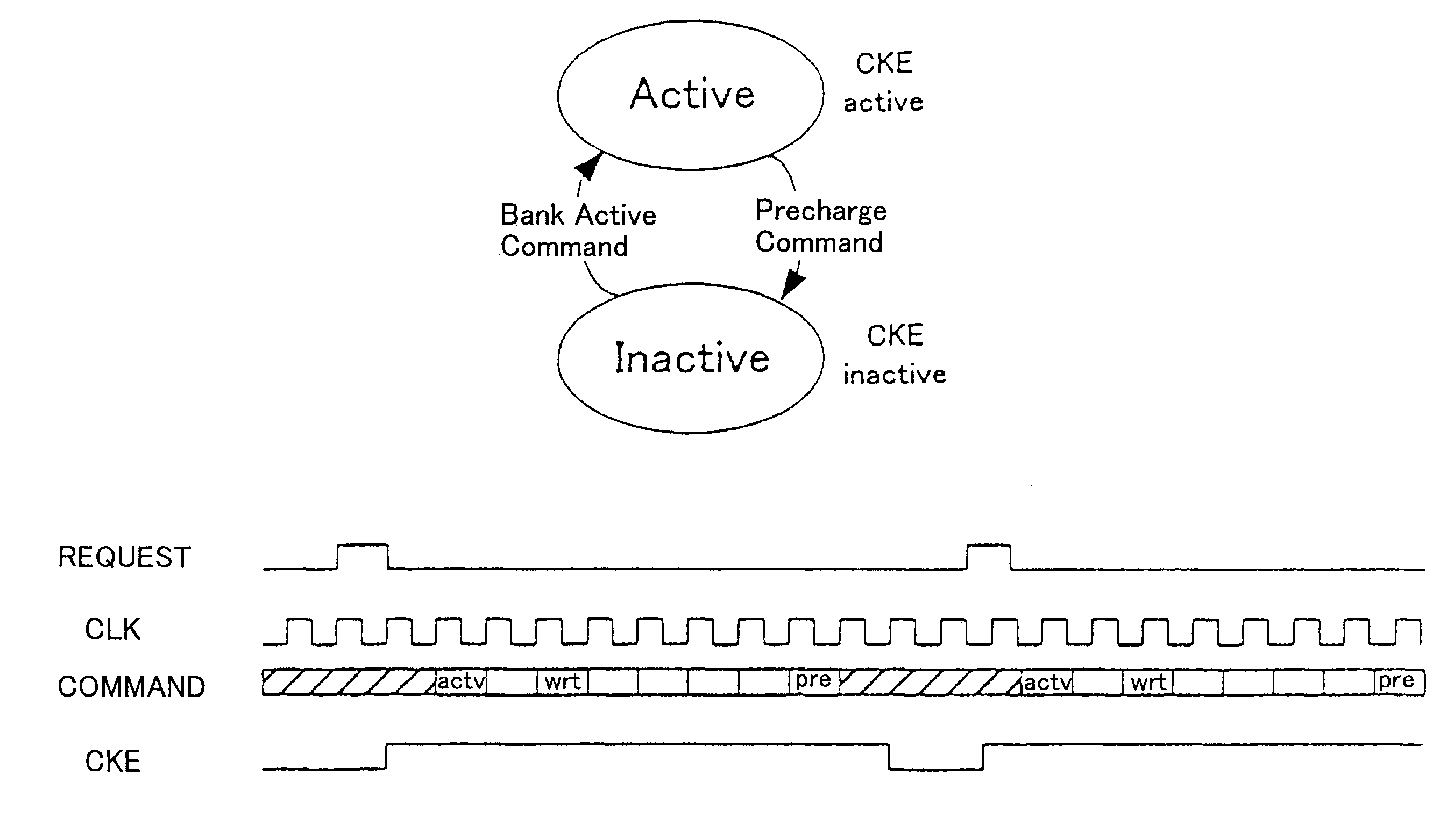
[0037]According to the clock control apparatus and method of the present invention, it is possible to efficiently carry out the power-saving clock control of the real-time processing SDRAM when a macro access including a sequence of several commands is given to the SDRAM by the request of the real-time processing. According to the present invention, not only the power-saving clock control of the SDRAM but also the power-saving clock control of the internal circuits of the memory controller can be realized.

Problems solved by technology

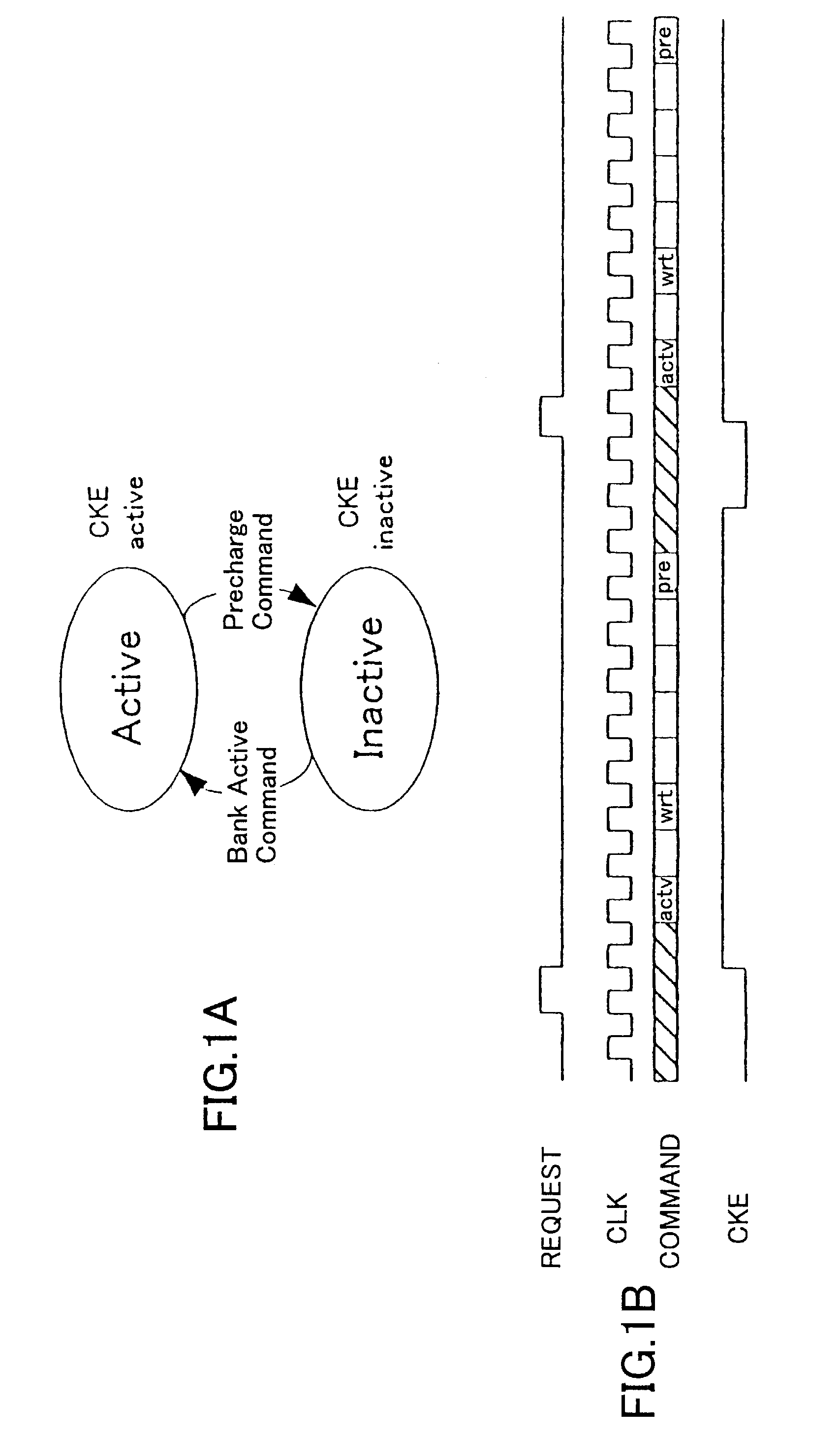
In the clock control by the general-purpose SDRAM controller as shown in FIG. 1B, there is the problem that it can respond only when the access unit is the single bank.
Moreover, in the case of the conventional general-purpose SDRAM controller, it is not taken into consideration about power saving of the internal circuit of the memory controller itself.

Method used


Image

  • Clock control apparatus and method, for a memory controller, that processes a block access into single continuous macro access while minimizing power consumption
  • Clock control apparatus and method, for a memory controller, that processes a block access into single continuous macro access while minimizing power consumption
  • Clock control apparatus and method, for a memory controller, that processes a block access into single continuous macro access while minimizing power consumption

Examples


Embodiment Construction

[0044]A description will now be given of preferred embodiments of the present invention with reference to the accompanying drawings.

[0045]FIG. 3 shows the composition of a memory controller 10 to which one preferred embodiment of the clock control apparatus of the present invention is applied.

[0046]FIG. 5 shows the composition of a system including the memory controller 10 shown in FIG. 3 and an SDRAM 20 for real-time-processing applications.

[0047]As shown in FIG. 3, the memory controller 10 of this embodiment comprises a system interface (SI) circuit 12, an access-control unit 14, and a power saving control unit 30.

[0048]The access-control unit 14 includes an address computation circuit 16 and a command sequence control circuit 18.

[0049]As shown in FIG. 5, this system 1 comprises the SDRAM 20, the memory controller 10, a phase-locked loop (PLL) circuit 40, and a plurality of modules 42-1, . . . , 42-m.

[0050]For example, the SDRAM 20 is formed as a video memory for MPEG applications...


PUM


Abstract

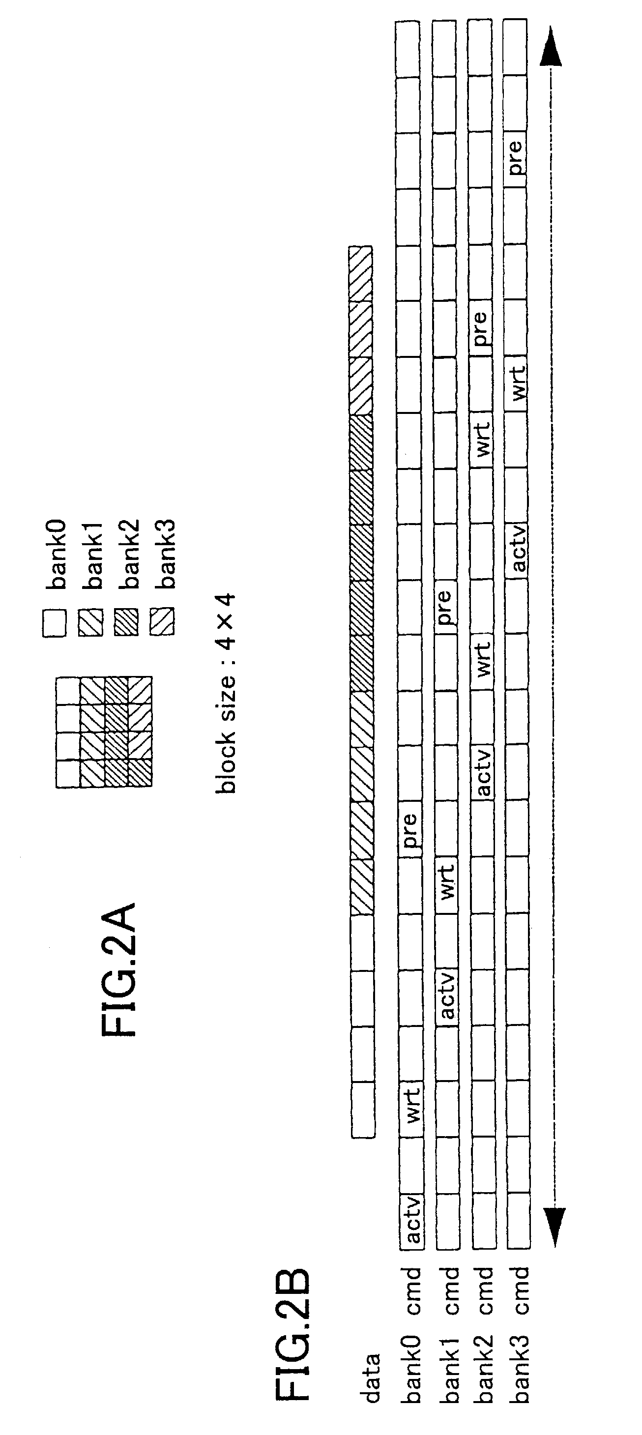
A clock control apparatus for a memory controller comprises an interface unit which processes a block access to a plurality of banks of an SDRAM as a single continuous macro access in order to perform arbitration of the macro access, the block access externally supplied to the memory controller. A power-saving control unit controls both a clock signal of an internal circuit of the memory controller and a clock enable signal of the SDRAM in response to a control signal supplied from the interface unit.

Description

CROSS-REFERENCE TO RELATED APPLICATION[0001]This application is based on Japanese priority application No. 2002-114295, filed on Apr. 17, 2002, the entire contents of which are hereby incorporated by reference.BACKGROUND OF THE INVENTION[0002]1. Field of the Invention[0003]The present invention relates to a clock control apparatus and method for a memory controller for reduction of power consumption. More specifically, the present invention relates to a clock control apparatus and method that controls the clock signal to an internal circuit of a memory controller and the clock enable signal CKE to SDRAM when accessing image data of SDRAM per block or per line.[0004]The clock control apparatus and method of the present invention are applicable to a memory controller of SDRAM for real-time processing applications, such as MPEG CODEC LSI or digital-broadcasting receivers, in order to effectively carry out reduction of power consumption of the memory controller when there is a definite ...

Claims


Application Information

Patent Timeline
IPC IPC(8): G06F1/26G06F1/32G06F12/00G06F12/06
CPCG06F1/3203G06F1/3275Y02B60/1228Y02B60/32Y02B60/1225Y02D10/00Y02D30/50
Inventor LI, JIANG
Owner FUJITSU LTD
Learn More