Magnetic head bar holding unit, lapping device, and method of lapping medium-opposing surface of thin-film magnetic head

a technology of magnetic head and holding unit, which is applied in the direction of manufacturing tools, instruments, record information storage, etc., can solve the problems of future reduction of achieve the effect of lowering the levitation of the thin-film magnetic head

Active Publication Date: 2006-08-08
TDK CORPARATION +1
View PDF5 Cites 18 Cited by
  • Summary
  • Abstract
  • Description
  • Claims
  • Application Information

AI Technical Summary

Benefits of technology

[0012]Each of the heaters in the respective thin-film magnetic head in the magnetic bar are electrically connected to its neighbors in series and a variable resister is connected to each heater in parallel. In such a configuration, each heater is energized so as to generate heat. As a consequence, it becomes possible to vary the resistance of the variable resistor for each heater so as to adjust the amount of current that flows to each heater, respectively, thereby making it possible to adjust the amount of projection in the medium-opposing surface of each thin-film magnetic head. Also, not so much equipment is needed for energizing and lapping a plurality of medium-opposing surfaces of the thin-film magnetic heads at a time. Therefore, the medium-opposing surface can be lapped well and efficiently in each thin-film magnetic head. As a result, even if the medium-opposing surface expands when the electromagnetic transducer is energized at the time of the actual recording onto a hard disk, the flying height of the thin-film magnetic head can be set to an appropriate value and contact between the thin-film magnetic head and the hard disk can be prevented, thereby lowering levitation of the thin-film magnetic head.
[0013]In this case, the thin-film magnetic head may be formed on a support and the heater is disposed on a surface of the thin-film magnetic head opposite from the support, thus making it unnecessary to form the heater within the thin-film magnetic head, and thus facilitating the manufacturing of the thin-film magnetic head.

Problems solved by technology

However, the conventional techniques mentioned above, may not fully prevent the projection of the medium-opposing surface, and thus, further reduction in the levitation of the thin-film magnetic head in the future will be difficult.
The inventors have also been studying the forming a heater for adjusting the gap between a magnetoresistive device and a hard disk in the thin-film magnetic head (not publicly known), and the problem mentioned above may occur in this case as well.

Method used


Image

  • Magnetic head bar holding unit, lapping device, and method of lapping medium-opposing surface of thin-film magnetic head
  • Magnetic head bar holding unit, lapping device, and method of lapping medium-opposing surface of thin-film magnetic head
  • Magnetic head bar holding unit, lapping device, and method of lapping medium-opposing surface of thin-film magnetic head

Examples


Embodiment Construction

[0039]In the following, preferred embodiments of the present invention will be explained in detail with reference to the accompanying drawings. In the figures, like reference numerals identify like elements.

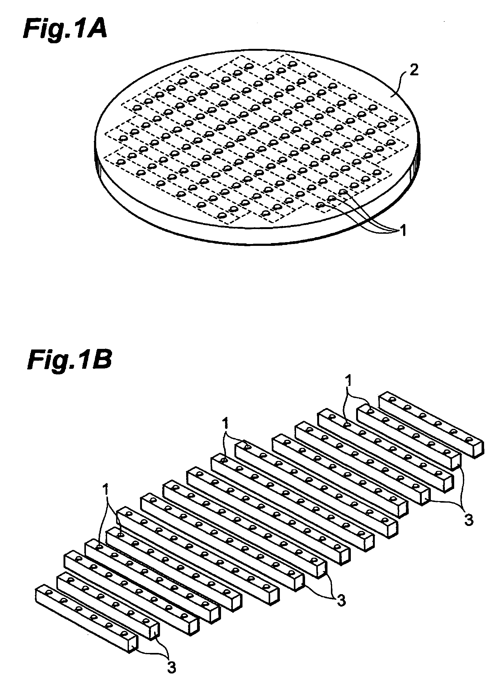
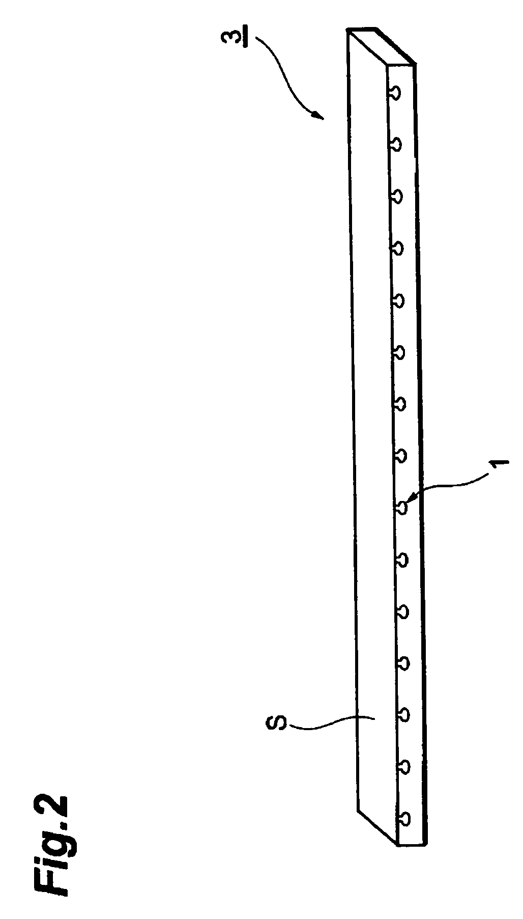
[0040]FIG. 1A shows thin-film magnetic heads 1 to which the lapping method in accordance with an embodiment according to the present invention is applied formed on a support 2 made of AlTiC (Al2O3.TiC) or the like. FIG. 1B shows the production of a plurality of magnetic head bars 3 (hereinafter, referred to as ‘bar’) each including thin-film magnetic heads 1 arranged in a row by cutting support 2.

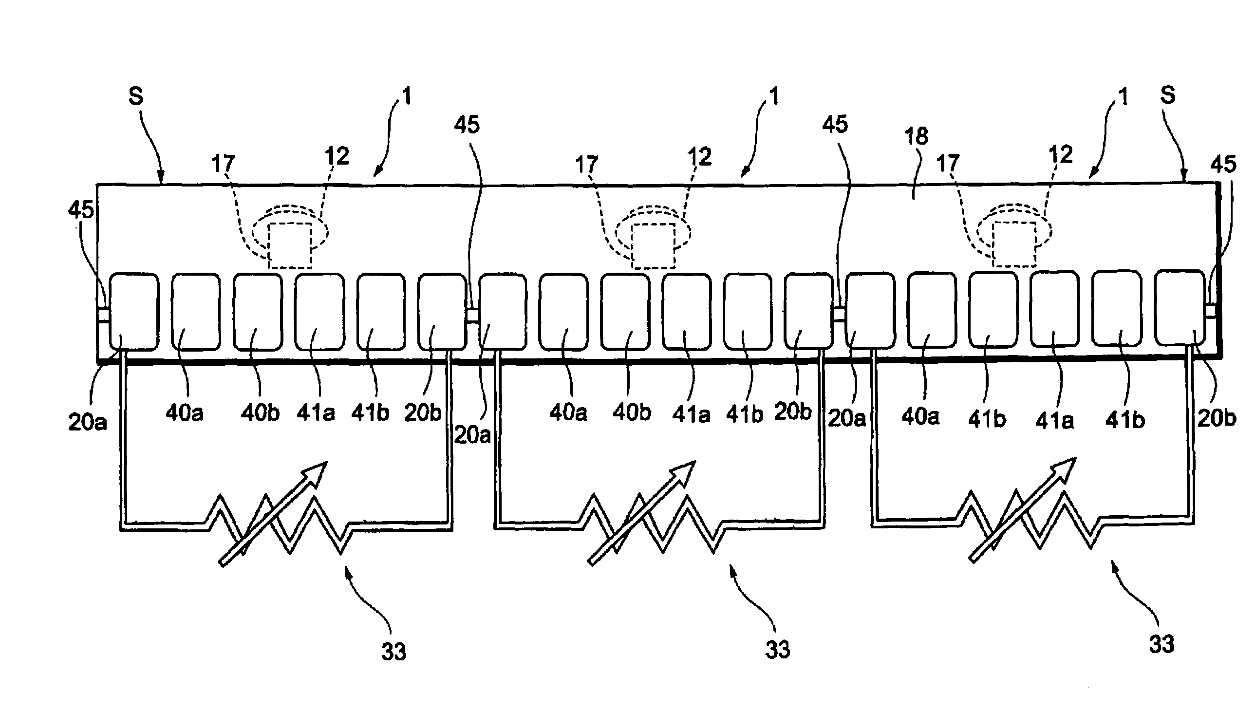
[0041]Polishing in the lapping method in accordance with this embodiment refers to one applied to a medium-opposing surface of a thin-film magnetic head of bar 3 in the stage shown in FIG. 1B before, after, or in the middle of lapping for adjusting the MR height or the like. The MR height refers to the distance in the depth direction of the magnetoresistive device for reproducing as seen...


PUM

PropertyMeasurementUnit
glass transition temperatureaaaaaaaaaa
thicknessaaaaaaaaaa
resistanceaaaaaaaaaa

Abstract

The heaters in the respective thin-film magnetic head in the bar are electrically connected to its neighbors, and a variable resistor is connected to each of the heaters in parallel. The resistance of each of the variable resistors is varied depending on the amount that the medium-opposing surface (ABS) of the thin-film magnetic head is to project. Also, the medium-opposing surface of the thin-film magnetic head in the magnetic head bar is polished while energizing all the heaters by the same power supply.

Description

BACKGROUND OF THE INVENTION[0001]1. Field of the Invention[0002]The present invention relates to a magnetic head bar holding unit, a lapping device, and a method of lapping medium-opposing surface (ABS) in a thin-film magnetic head.[0003]2. Related Background Art[0004]In general, a head gimbals assembly (HGA) is constructed by attaching a head slider formed with a thin-film magnetic head to a leading end of a flexible arm member such as a suspension. This head gimbals assembly is built in a hard disk drive (HDD) and carries out recording / reproducing to a hard disk that is a recording medium. At the time of recording / reproducing, an airflow that accompanies the rotation of the hard disk passes under the thin-film magnetic head, thereby levitating the magnetic head from the hard disk. As the recording density on the hard disk increased, the gap between the thin-film magnetic head and the hard disk, i.e., head flying height, has decreased to 10 nm, which currently seems to be the limit...

Claims


Application Information

Patent Timeline
Patent Type & Authority Patents(United States)
IPC IPC(8): B24B49/00B24B1/00B24B51/00G11B5/127B24B7/00G11B5/31
CPCG11B5/31Y10T29/49032
Inventor OYAMA, NOBUYAOTA, NORIKAZUKOIDE, SOJISASAKI, TETSUROFUKUROI, OSAMU
Owner TDK CORPARATION
Why Eureka
Try Eureka