

Steerable segmented endoscope and method of insertion
- Summary
- Abstract
- Description
- Claims
- Application Information
AI Technical Summary
Benefits of technology
Problems solved by technology
Method used
Image

Examples
first embodiment
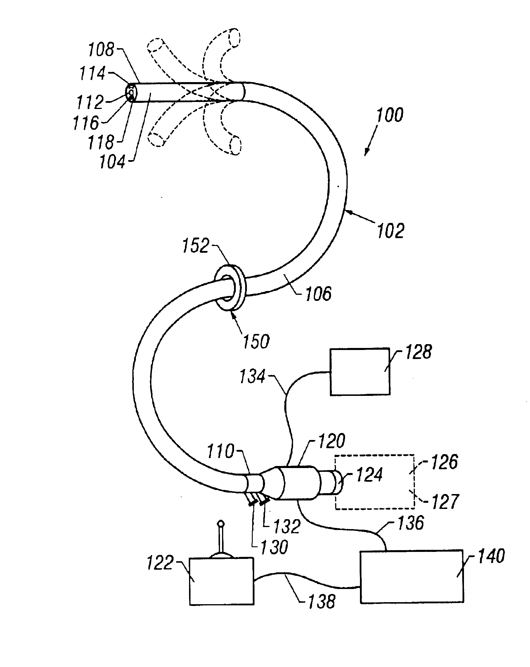
[0031]FIG. 2 shows the steerable endoscope 100 of the present invention. The endoscope 100 has an elongate body 102 with a manually or selectively steerable distal portion 104 and an automatically controlled proximal portion 106. The selectively steerable distal portion 104 can be selectively steered or bent up to a full 180 degree bend in any direction. A fiberoptic imaging bundle 112 and one or more illumination fibers 114 extend through the body 102 from the proximal end 110 to the distal end 108. Alternatively, the endoscope 100 can be configured as a video endoscope with a miniaturized video camera, such as a CCD camera, positioned at the distal end 108 of the endoscope body 102. The images from the video camera can be transmitted to a video monitor by a transmission cable or by wireless transmission where images may be viewed in real-time or recorded by a recording device onto analog recording medium, e.g., magnetic tape, or digital recording medium, e.g., compact disc, digita...
second embodiment
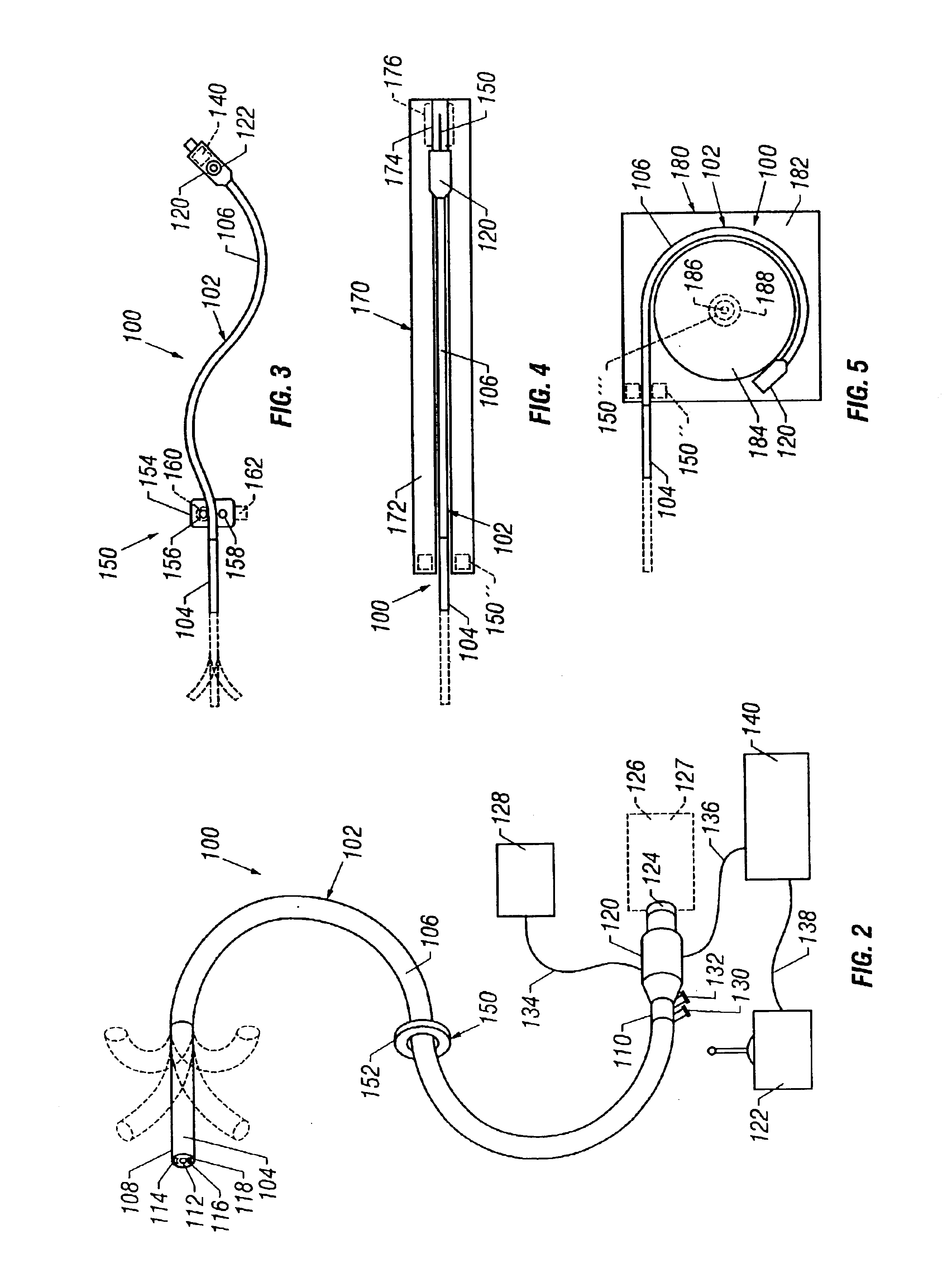
[0035]FIG. 3 shows the endoscope 100 of the present invention. As in the embodiment of FIG. 2, the endoscope 100 has an elongate body 102 with a selectively steerable distal portion 104 and an automatically controlled proximal portion 106. The steering control 122 is integrated into proximal handle 120 in the form or one or two dials for selectively steering, the selectively steerable distal portion 104 of the endoscope 100. Optionally, the electronic motion controller 140 may be miniaturized and integrated into proximal handle 120, as well. In this embodiment, the axial motion transducer 150 is configured with a base 154 that is attachable to a fixed point of reference, such as the surgical table. A first roller 156 and a second roller 158 contact the exterior of the endoscope body 102. A multi-turn potentiometer 160 or other motion transducer is connected to the first roller 156 to measure the axial motion of the endoscope body 102 and to produce a signal indicative of the axial p...
third embodiment
[0037]FIG. 4 shows the endoscope 100 of the present invention, which utilizes an elongated housing 170 to organize and contain the endoscope 100. The housing 170 has a base 172 with a linear track 174 to guide the body 102 of the endoscope 100. The housing 170 may have an axial motion transducer 150′ that is configured as a linear motion transducer integrated into the linear track 174. Alternatively, the housing, 170 may have an axial motion transducer 150″ configured similarly to the axial motion transducer 150 in FIG. 2 or 3. The endoscope 100 may be manually advanced or withdrawn by the user by grasping the body 102 distal to the housing 170. Alternatively, the housing 170 may include a motor 176 or other linear motion actuator for automatically advancing and withdrawing the body 102 of the endoscope 100. In another alternative configuration, a motor with friction wheels, similar to that described above in connection with FIG. 3, may be integrated into the axial motion transducer...
PUM
 Abstract
Description
Claims
Application Information