Antenna matching circuit, mobile communication device including antenna matching circuit, and dielectric antenna including antenna matching circuit

Inactive Publication Date: 2006-08-08
TAIYO YUDEN KK
View PDF12 Cites 185 Cited by
  • Summary
  • Abstract
  • Description
  • Claims
  • Application Information

AI Technical Summary

Benefits of technology

[0012]To attain the aforementioned object, as an antenna band widening means according to the present invention, a parallel resonant matching circuit including a series resonant portion is proposed. Unlike a susceptance compensation method of perfo

Problems solved by technology

However, according to the aforementioned matching means, a matching property in a chip antenna alone is improved, but

Method used


Image

  • Antenna matching circuit, mobile communication device including antenna matching circuit, and dielectric antenna including antenna matching circuit
  • Antenna matching circuit, mobile communication device including antenna matching circuit, and dielectric antenna including antenna matching circuit
  • Antenna matching circuit, mobile communication device including antenna matching circuit, and dielectric antenna including antenna matching circuit

Examples


modification examples

[0057](Modification examples of the Embodiment)

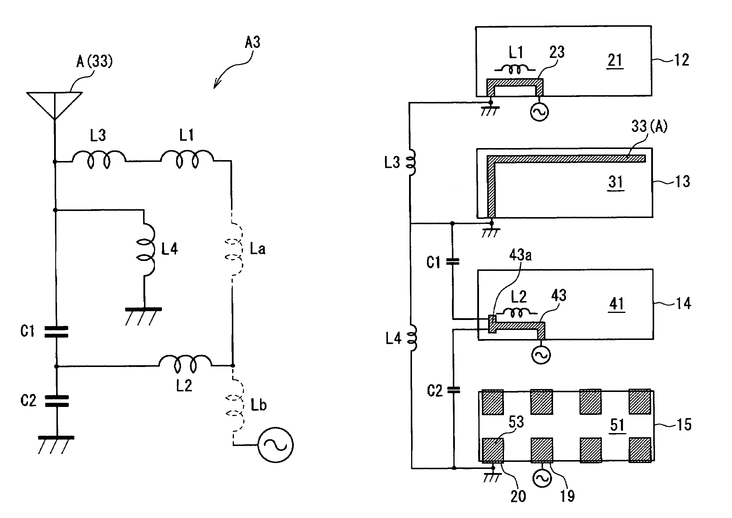
[0058]Subsequently, a first modification example of this embodiment will be explained based on FIG. 12 to FIG. 14. As shown in FIG. 13, a dielectric antenna 61 includes an antenna (radiation element) A and an antenna matching circuit A6. A parallel resonant section 3 included in the antenna matching circuit A6 is composed of an inductance component L1 and a capacitance component C which are connected in series and an inductance component L2 and an inductance component L3 which are connected in series.

[0059]Here, the inductance component L3 is formed by a first matching element 64 having an upside-down U shape on an element forming surface of a first substrate 63. One end of the first matching element 64 is connected to a power feeding terminal 29, and the other end thereof is connected to a GND terminal 30. A radiation element 66 having a substantially L shape is formed on an element forming surface of a second substrate 65. The radiati...


PUM


Abstract

In an antenna matching circuit including a parallel resonant section connected to a radiation element constituting an antenna, the parallel resonant section includes a series resonant portion composed of an inductance component and a capacitance component. The series resonant portion realizes antenna matching and band widening. The parallel resonant section can be inserted in a feeder line connected to the radiation element or inserted in a GND line connected to the radiation element.

Description

FIELD OF THE INVENTION[0001]The present invention relates to an antenna matching circuit, a mobile communication device including an antenna matching circuit, and a dielectric antenna including an antenna matching circuit.BACKGROUND OF THE INVENTION[0002]As antenna matching technology on the aforementioned antenna matching circuit and the like, for example, the following are known.[0003]Patent Document 1 Japanese Patent Application Laid-open No. Hei 5-327331.[0004]A matching means described in Patent Document 1 uses a parallel resonant circuit composed of one L and one C, and it is known as a susceptance compensation method (See paragraph numbers 0006, 0007, FIGS. 2, 4, 6). Patent Document 2 Japanese Patent Application Laid-open No. 2000-286615[0005]A matching means described in Patent Document 2 uses a π-type tuning circuit, and this matching means is also commonly known as an antenna matching means (See a paragraph number 0022, FIG. 4).[0006]Each of the aforementioned documents di...

Claims


Application Information

Patent Timeline
IPC IPC(8): H01Q1/50H03H7/38H01Q1/38H03H5/02H03H7/01
CPCH03H7/38H03H7/0115H03H2001/0085
Inventor IMAIZUMI, TATSUYA
Owner TAIYO YUDEN KK
Why Eureka
Try Eureka