Particle counter with self-concealing aperture assembly

a particle counter and aperture assembly technology, applied in the field of particle measurement systems, can solve the problems of inability to effectively reduce optical noise, scattered light noise floor of the system, and very different operation principles so as to eliminate scattered light noise, and reduce the scattered light noise of the particle measurement system or particle counter.

Active Publication Date: 2006-08-08
PARTICLE MEASURING SYST
View PDF3 Cites 35 Cited by
  • Summary
  • Abstract
  • Description
  • Claims
  • Application Information

AI Technical Summary

Benefits of technology

[0019]To reduce scattered light noise of a particle measurement system or particle counter, a self-concealing aperture is utilized. In one embodiment, an aperture assembly may be self-concealing by having at least a portion of the aperture assembly operate as a beam stop extending into a sample chamber. In a second embodiment, the aperture assembly may have a smooth, reflective inside surface of the aperture assembly to provide for self-concealment. In the case of the aperture assembly having an extended portion to operate as the beam stop, light reflected from the inside surfa

Problems solved by technology

These latter systems rely on collecting scattered light from thousands, millions, and even billions of particles; therefore, their principles of operation are very different from the principles used in particle counters, which detect individual particles suspended in a fluid.
One limitation of the single component collecting system is the inherent inability to effectively reduce optical noise known as the scattered light noise floor of the system.
Unlike multiple component collecting systems that have the ability to remove the laser aperture assembly from direct view of the photo-diode, a single component system has limited options when dealing with scattered light.
The spontaneous emission light generated by the facet is not coherent and cannot be successfully shaped and imaged by lenses of the laser diode module 116.
Unfortunately, the aperture assembly 120 inherently prod

Method used


Image

  • Particle counter with self-concealing aperture assembly
  • Particle counter with self-concealing aperture assembly
  • Particle counter with self-concealing aperture assembly

Examples


Embodiment Construction

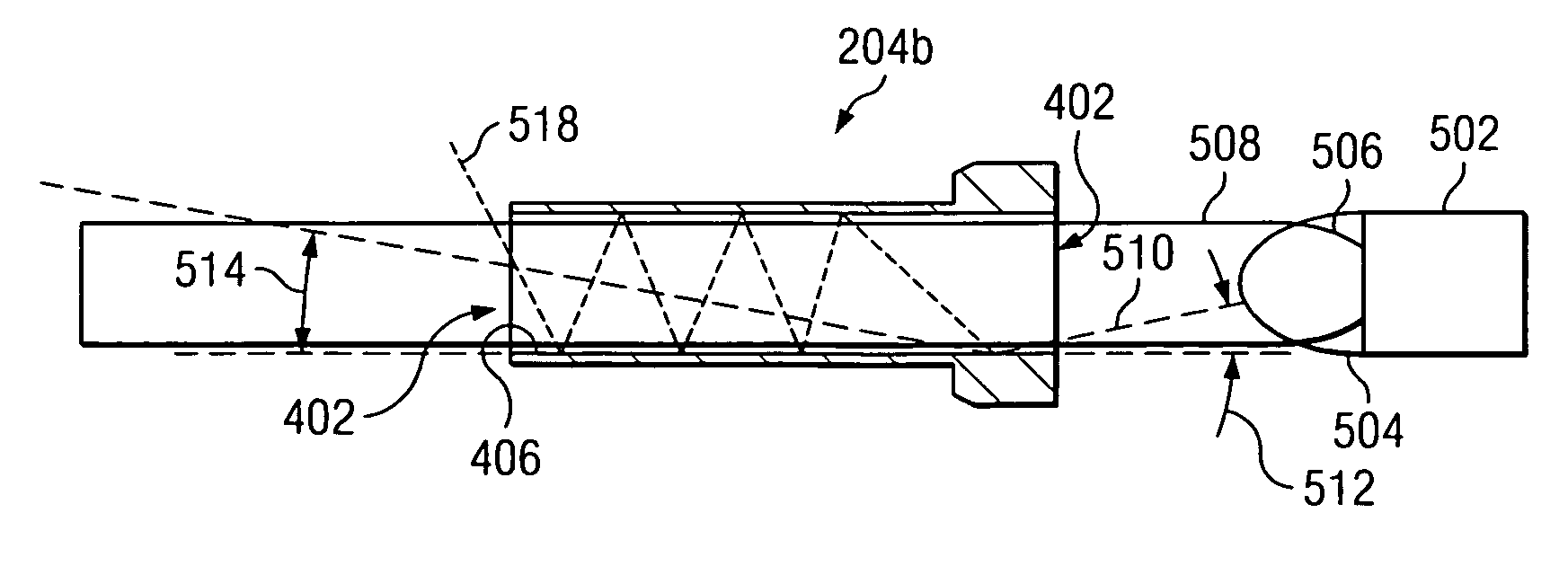
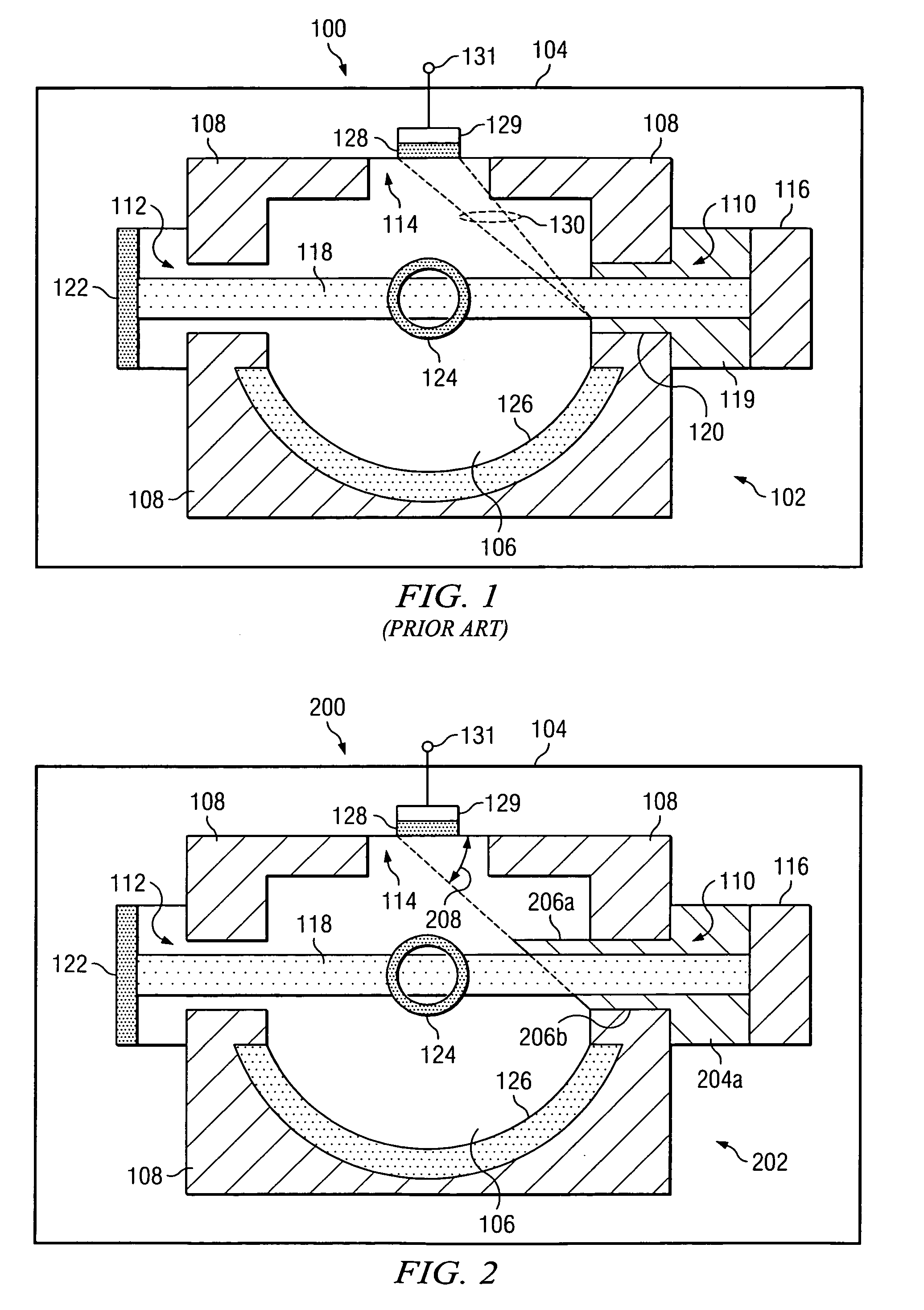
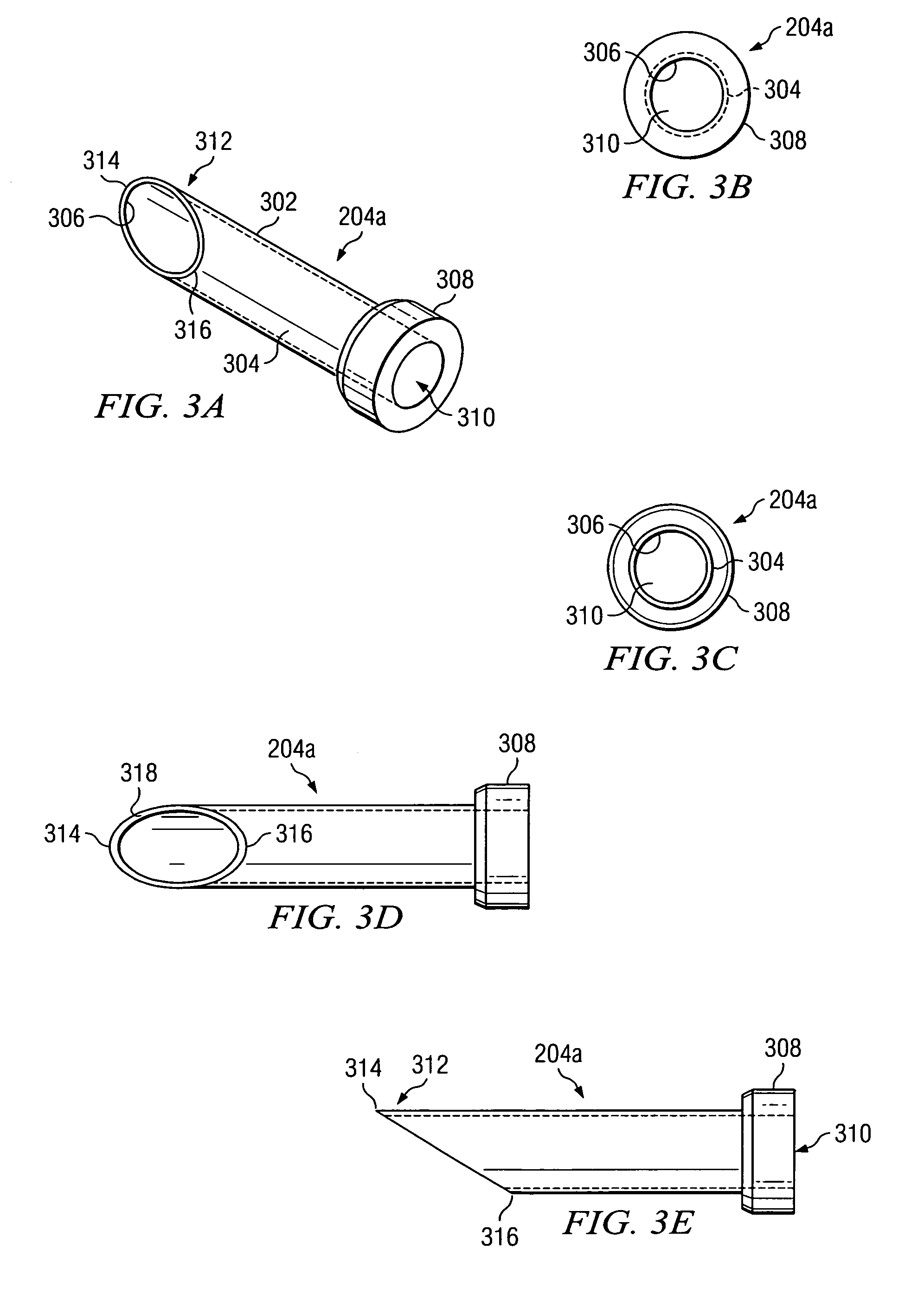
[0030]FIG. 2 is a schematic of a particle counter or particle measurement system 200 including a single component light collecting system according to the principles of the present invention. As shown, the particle measurement system 200 is composed of many of the same parts as the conventional particle measurement system 100 of FIG. 1. For example, the particle measurement system includes a single component light collecting system 202 that includes sample chamber 106, frame 108, apertures 110, 112, and 114, laser diode module 116, beam stop 122, inlet orifice 124, collecting mirror 126, light detector 128, signal processor / amplifier 129, and output 131. However, the particle measurement system 200 uses alternative components for performing measurement of particles of gas, such as air, to substantially eliminate scattered light noise. For example, the particle measurement system 200 may include an aperture assembly 204a according to the principles of the present invention.

[0031]Alth...


PUM


Abstract

A particle measurement system using a single component light collecting system with an aperture having a portion within direct view of the light detector. An aperture assembly extending into a sample may be self-concealing by having an extended portion to block light from directly illuminating the light detector. Alternatively, a smooth, reflective inside surface of the aperture assembly provides for self-concealment by causing spontaneous emitted light to have low angles of reflection. In either case, spontaneously emitted light is substantially prevented from reflecting directly into the light detector, thereby reducing light noise to the level of molecular noise.

Description

RELATED APPLICATION[0001]This application claim benefit of U.S. Provisional Application No. 60 / 657,626 filed Mar. 1, 2005.BACKGROUND OF THE INVENTION[0002]1. Field of the Invention[0003]The principles of the present invention are directed to a particle measurement system, and more particularly, but not by way of limitation, to a particle sensor having a single component collecting system.[0004]2. Description of Related Art[0005]Most people are familiar with the sight of dust in a sunbeam. Four things that are necessary for this include: sunlight (to illuminate the dust), dust (to reflect the sunlight), air (to carry the dust), and a person's eye (to see the dust, or more specifically to see the light reflected by the dust). An optical particle counter uses the same principles, but refines them to maximize its effectiveness. In modern particle counters, a laser light source is typically used, the sample (e.g., air) is controlled, and a high sensitivity photo or light detector is util...

Claims


Application Information

Patent Timeline
IPC IPC(8): G01N21/00
CPCG01N15/1459G01N15/1434G01N2015/1486
Inventor BATES, THOMASMILLER, RICHARD O.ALEXANDER, RICHARD A.
Owner PARTICLE MEASURING SYST
Why Eureka
Try Eureka