Ethernet switching architecture and dynamic memory allocation method for the same

Inactive Publication Date: 2006-08-08
ADMTEK INCORPORATED
View PDF1 Cites 5 Cited by
  • Summary
  • Abstract
  • Description
  • Claims
  • Application Information

AI Technical Summary

Benefits of technology

[0036]One object of this invention is to solve the above-mentioned problems of the limitations in transmission bandwidth and transmission port counts for Ethernet switching. Another object of this invention is to provide a method for dynamically allocating memories in Ethernet switching architecture in order to increase transmission bandwidth for Ethernet switching and make it workable to increase transmission port counts.
[0038]Through this method, the time required for the linking process can be reduced by half comparing to a conventional technique. Besides, the packet used a “single link address” to form a “single linked list” and write the entire block addresses of the packet segments onto the shared memory “in one single process”. For this, when making and reading links, the time required is irrelevant to the allocated block counts on the shared memory. Consequently, the total packet transmission time is reduced to the product of two times the clock period and transmission port counts. Hence, without increasing the clock speed, not only a high bandwidth can be obtained, but also the transmission port counts can be increased at the same time.

Problems solved by technology

This is simple for hardware configuration, however, the length of the received packet could be considerably smaller than the fixed length and the usage efficiency would dramatically reduced.
However, in high speed Ethernet switching, under the demand of the transmission time for a packet to be smaller than 672 ns (that is, the bandwidth is 1 Gb / s and above), the transmission port counts that is proportional to the transmitting time of the packet would be limited.
However, this will cause the power consuming and poor reliability problems.

Method used


Image

  • Ethernet switching architecture and dynamic memory allocation method for the same
  • Ethernet switching architecture and dynamic memory allocation method for the same
  • Ethernet switching architecture and dynamic memory allocation method for the same

Examples


Embodiment Construction

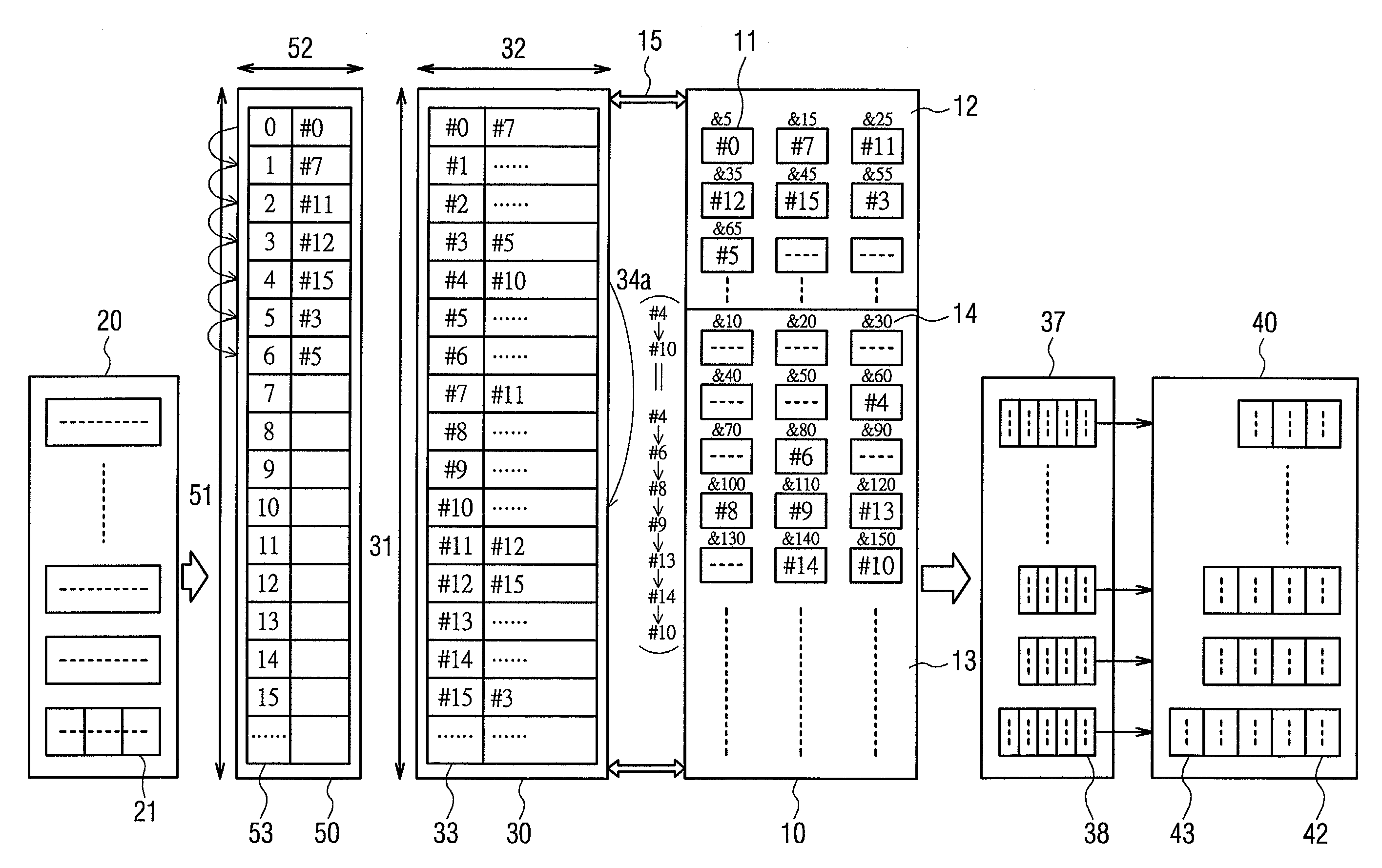
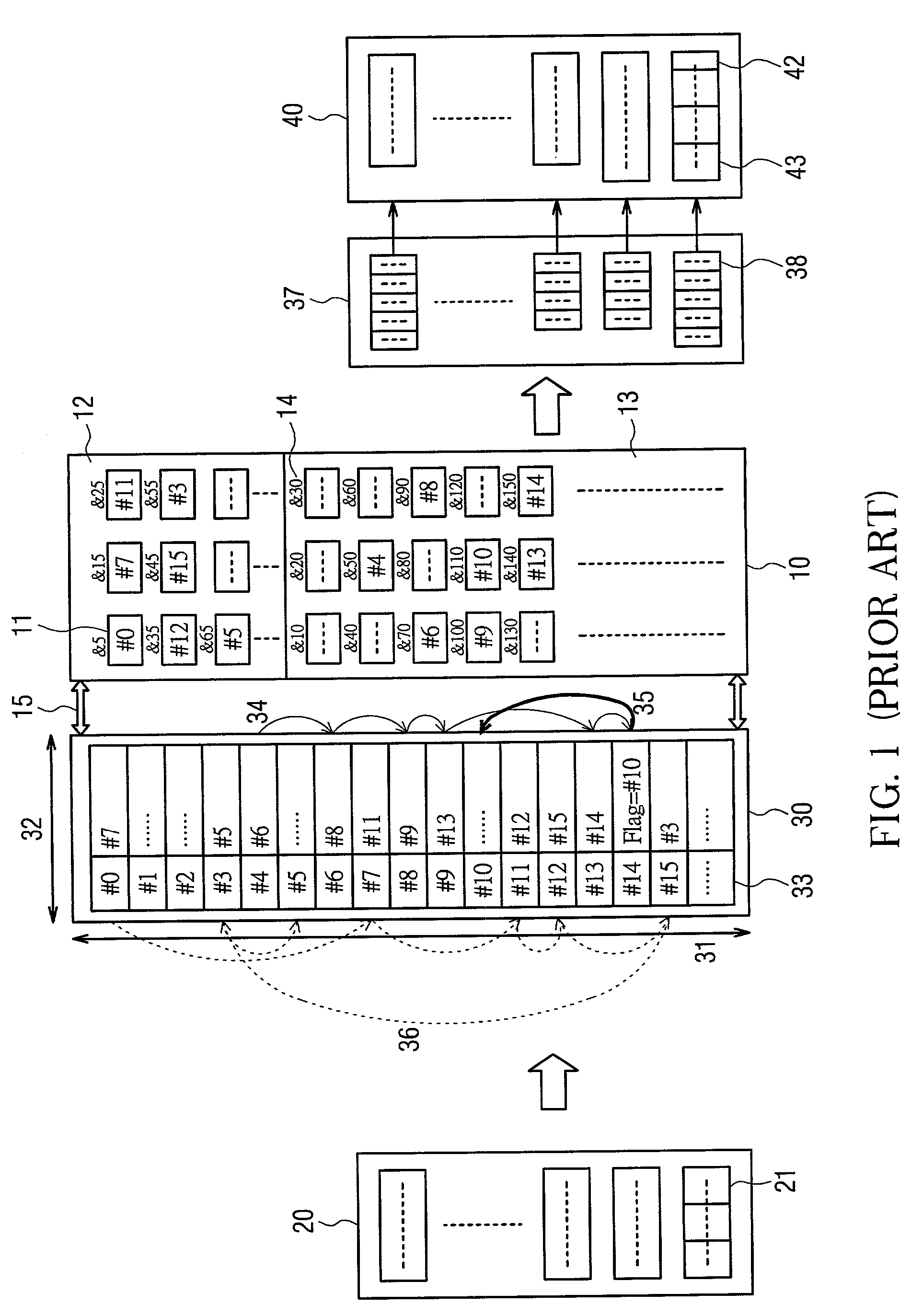
[0047]FIG. 4 is a schematic block diagram according to one embodiment of the present invention for an Ethernet switching architecture in which the same number is referring to the same component as in FIG. 1. Comparing to FIG. 1, the present invention provided with a free-link RAM 50 serving as a FIFO device and a preferred “single” linked list 34a. Among these, the number of free-link address spaces 51 on the free-link RAM 50 and the number on the link address spaces 31 of the link RAM 30 are both configured to be the same as the block counts on the shared memory 10. In addition, the free-link address width 52 of the free-link RAM 50 is smaller than the link address width 32 of the link RAM 30. As a result, an obtaining of the link address spaces before a linked list of a plurality of packet segments of a packet been made and a releasing of the link address spaces after the linked list been read can be co-managed.

[0048]For instance, the six packet segments of a received packet are s...


PUM


Abstract

This invention discloses a dynamic memory allocation method for an Ethernet switching architecture, which can resolve problems with the limitations of transmission bandwidths and transmission port counts in a conventional network packet switching. The method comprises steps of providing a plurality of input ports and output ports, providing a shared memory for storing packet segments of a plurality of packets, providing a first link RAM (Random Access Memory) for controlling a making and reading of a single linked list for the packet segments of each the plurality of packets, and providing a second link RAM serving as a FIFO (first in first out) device for co-managing an obtaining of the link address spaces at the corresponding input ports before the single linked list been made, and a releasing of the link address spaces at the corresponding output ports after the single linked list been read.

Description

BACKGROUND OF THE INVENTION[0001]1. Field of the Invention[0002]The present invention relates to a method for dynamically allocate memories in an Ethernet switching architecture. More specifically this invention relates to an Ethernet switching architecture provided with an optimized single linked list for dynamically allocate a shared memory through a free-link RAM during the packet receiving & transmitting process, in order to achieve the object of improving the transmission bandwidth of network switching.[0003]2. Description of the Related Art[0004]A shared memory architecture is one that uses a single common memory as a switching device for network packets between the input ports and output ports. Through the path of data receiving of an input port, a received packet can be stored on the shared memory and can be assigned and transmitted to the path of data transmitting of an appropriate output port. And it is often used as a main structure for LAN (Local Area Network) switching ...

Claims


Application Information

Patent Timeline
IPC IPC(8): H04L12/28H04L12/56
CPCH04L49/351H04L49/103H04L49/3027
Inventor HSU, MENG-CHILO, WEI-REN
Owner ADMTEK INCORPORATED
Why Eureka
Try Eureka