Optical fiber coupling and inline fault monitor device and method

a technology of optical fiber and fault monitor, applied in the field of sensors, can solve the problems of troubleshooting, unknow whether, and damage to the optical fiber itself, and achieve the effect of facilitating the flow of ligh

Active Publication Date: 2006-08-08
LOCKHEED MARTIN CORP
View PDF13 Cites 77 Cited by
  • Summary
  • Abstract
  • Description
  • Claims
  • Application Information

AI Technical Summary

Benefits of technology

[0009]A sensor according to an aspect of the invention, for use in conjunction with light flow through a junction or gap between first and second optical fibers, comprises an alignment sleeve including first and second ends. The first and second ends of the alignment sleeve are dimensioned to accommodate ends of first and second optical fiber ferrules, respectively. The alignment sleeve, when assembled with the ferrules, coaxially aligns the associated first and second optical fibers, respectively, to thereby facilitate the flow of light across a gap between the first and second optical fibers. The sensor includes an optical sensor located adjacent the gap, for generating an electrical signal representative of light leaking from the gap. An indication arrangement is responsive to the electrical signal for providing an indication of light flow through the gap.

Problems solved by technology

This could be the case, for example, in a shipboard environment in which communications are accomplished by means of such optical fibers, and the optical fibers themselves, and the sources and sinks of information, are subject to damage due to collision or hostile action.
A disadvantage of the patch-panel routing suggested by FIG. 1 is that troubleshooting is somewhat difficult, in that a problem is usually manifested as a failure of a system including at least a source of optical signals and a sink of optical signals, joined by at least two separate optical fibers and a junction connector.
When a failure of such a system is suspected, it is initially not known whether the problem lies in the source, the sink, or the interconnecting optical fibers.
While the described testing is tedious but reasonably efficient, the difficulties become greater when the equipments to which the optical fibers are connected lie at remote locations relative to the patch panel 20 of FIG. 1.
In complex systems with hundreds of optical fibers, the testing may result in long down times.
In general, the repeater or junction boxes have relatively limited bandwidth, and are complex and expensive, and the automatic analysis arrangements are complex and expensive.
The automatic analysis system uses a bypass fiber, and its manufacturing is complex.

Method used


Image

  • Optical fiber coupling and inline fault monitor device and method
  • Optical fiber coupling and inline fault monitor device and method
  • Optical fiber coupling and inline fault monitor device and method

Examples


Embodiment Construction

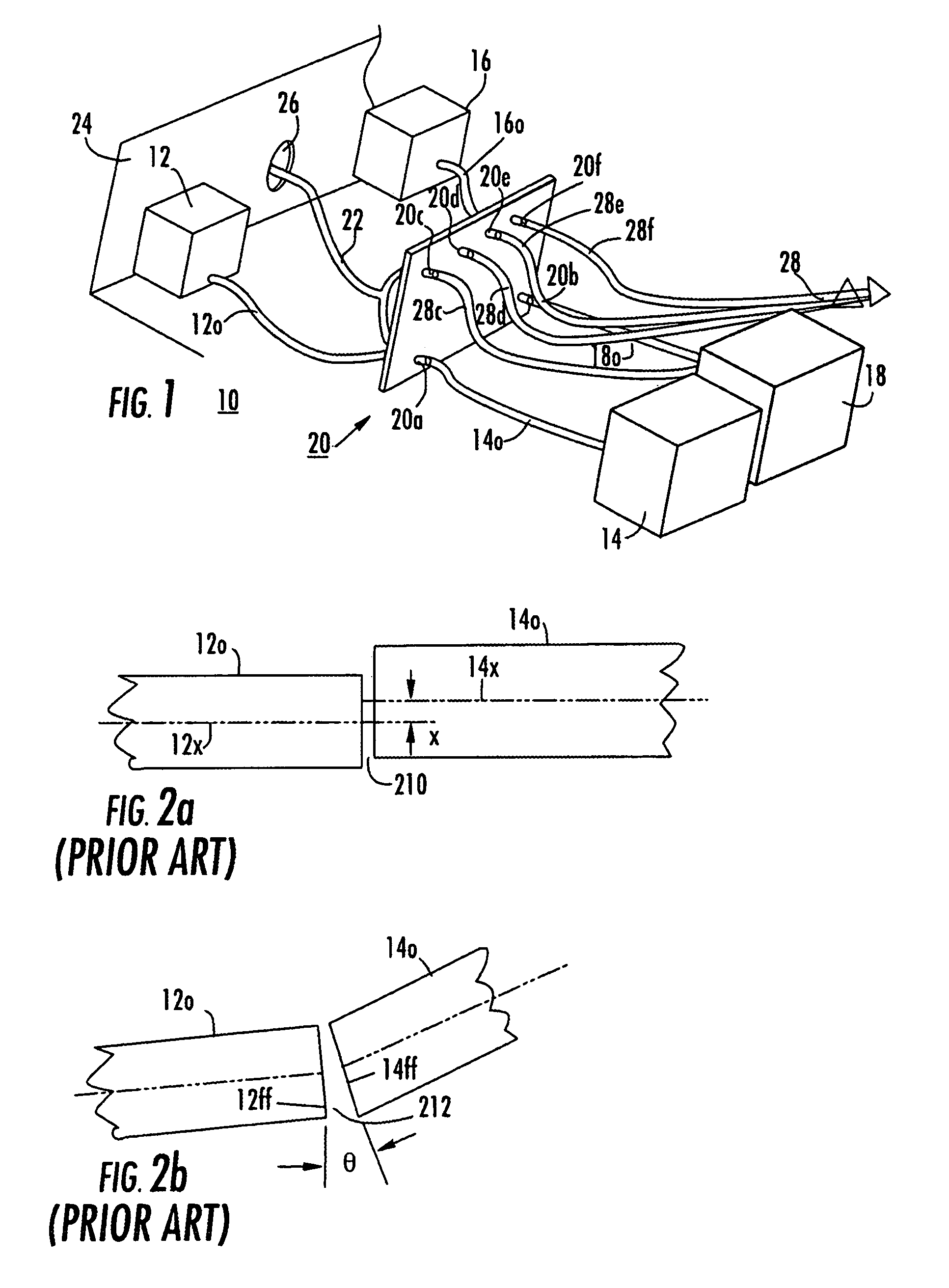
[0021]One way optical fibers are connected is by butting together flat end faces of the optical fibers. FIGS. 2a and 2b illustrate two possible types of optical fiber misalignment, as described at page 154 in the text FIBER OPTICS AND OPTOELECTRONICS, second edition, by Peter K. Cheo, published 1990 by Prentice-Hall, ISBN 0-13-315045-3. In FIG. 2a, the axis 12x of optical fiber 12o is offset by a distance x from the axis 14x of optical fiber 14o, so the gap 210 between the ends of the fibers has constant thickness or spacing. In FIG. 2b, the front faces 12ff and 14ff of optical fibers 12a and 14a, respectively, are skewed by an angle designated Θ to create a gap 212 of varying width.

[0022]The skewing or offset of the two fibers as described in conjunction with FIGS. 2a and 2b tends to cause some of the light traveling through the gap between the leak, so that the receiving optical fiber receives less light than might otherwise be expected. Also, some of the light arriving at the gap...


PUM


Abstract

An optical fiber connection arrangement includes an alignment sleeve for coaxially aligning optical fibers mounted in ferrules. A gap between the ends of the optical fibers allows some light to escape. A sensor responds to the leaked light, and the resulting signal is processed to determine whether light signal is present or absent.

Description

FIELD OF THE INVENTION[0001]This invention relates to sensors for use in conjunction with optical fiber systems, for aiding in monitoring and verification of signal flow.BACKGROUND OF THE INVENTION[0002]Many communication systems rely on optical fibers for carrying signals, because of the very high bandwidth of optical fibers. In complex systems, it may be desirable to be able to route signals on a particular optical fiber to a given one of a plurality of sources or sinks of optical signals. This could be the case, for example, in a shipboard environment in which communications are accomplished by means of such optical fibers, and the optical fibers themselves, and the sources and sinks of information, are subject to damage due to collision or hostile action. In such an event, it is desirable to be able to disconnect an optical fiber from a failed unit and to reconnect it to an operable unit of the same (or possibly of a different) type.[0003]FIG. 1 represents a prior-art arrangemen...

Claims


Application Information

Patent Timeline
Patent Type & Authority Patents(United States)
IPC IPC(8): G02B6/26G02B6/42
CPCG01M11/37G02B6/3807H04B10/07955G02B6/3897G02B6/385
Inventor GERSHMAN, VLADIMIR
Owner LOCKHEED MARTIN CORP
Why Eureka
Try Eureka