System for operating an Ethernet data network over a passive optical network access system

a passive optical network access and ethernet data technology, applied in the field of data communication networks, can solve the problems of ethernet operation becoming problematic, ethernet relies on a shared bus architecture which is not particularly suited to applications, and the possibility of collision, so as to increase the applicability of ethernet data networks

Inactive Publication Date: 2006-08-08
WSOU INVESTMENTS LLC +1
View PDF14 Cites 75 Cited by
  • Summary
  • Abstract
  • Description
  • Claims
  • Application Information

AI Technical Summary

Benefits of technology

[0012]The present invention is directed to a data communications system which overcomes many of the aforementioned limitations of known systems. The present invention provides a means of increasing the applicabilit

Problems solved by technology

Ethernet relies on a shared-bus architecture which is not particularly suited to applications where distances between users are substantially longer, such as in residential applications.
PONs are cost-effective largely because the expensive distribution fiber and head-end e

Method used


Image

  • System for operating an Ethernet data network over a passive optical network access system
  • System for operating an Ethernet data network over a passive optical network access system
  • System for operating an Ethernet data network over a passive optical network access system

Examples


Embodiment Construction

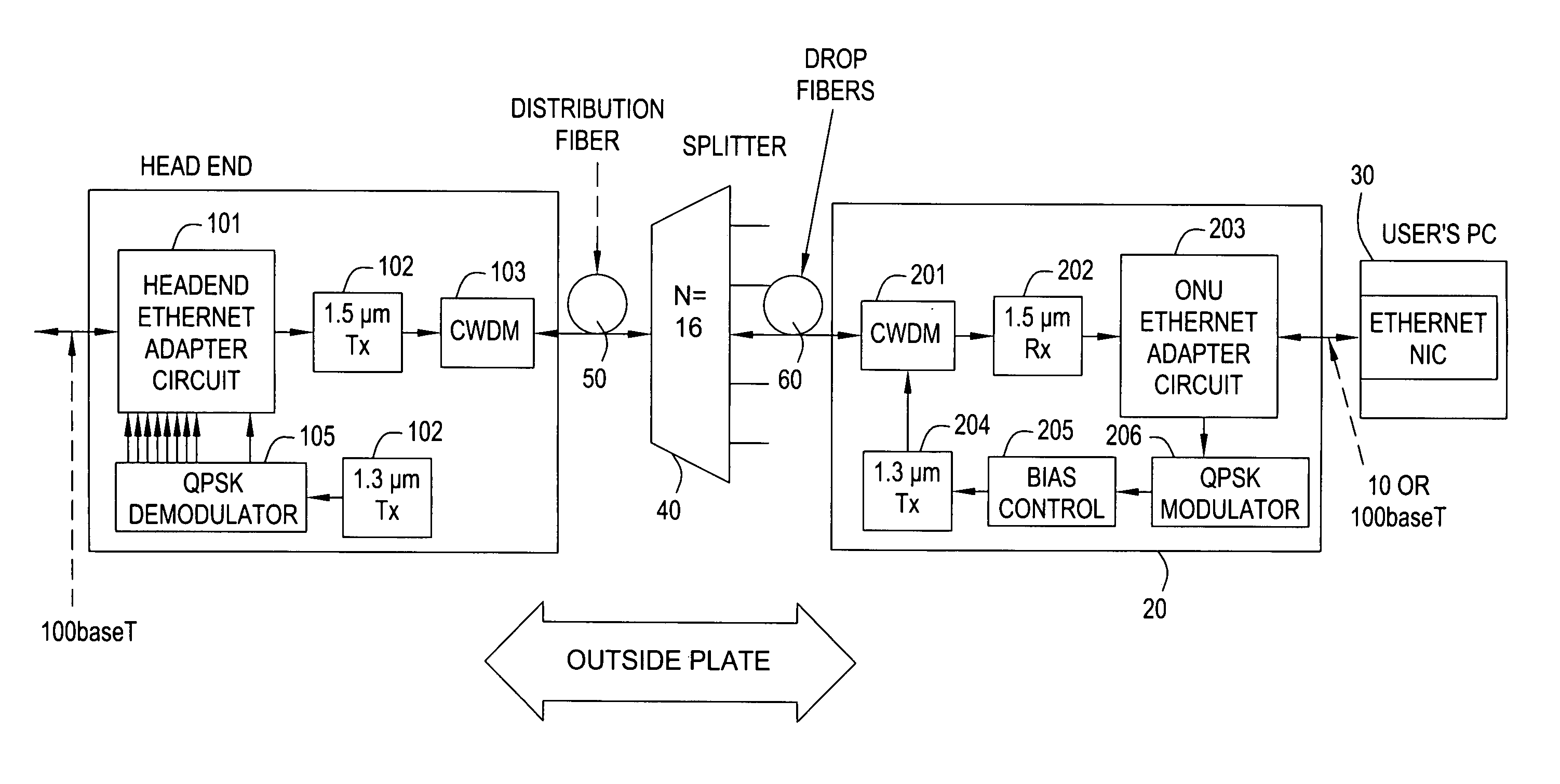
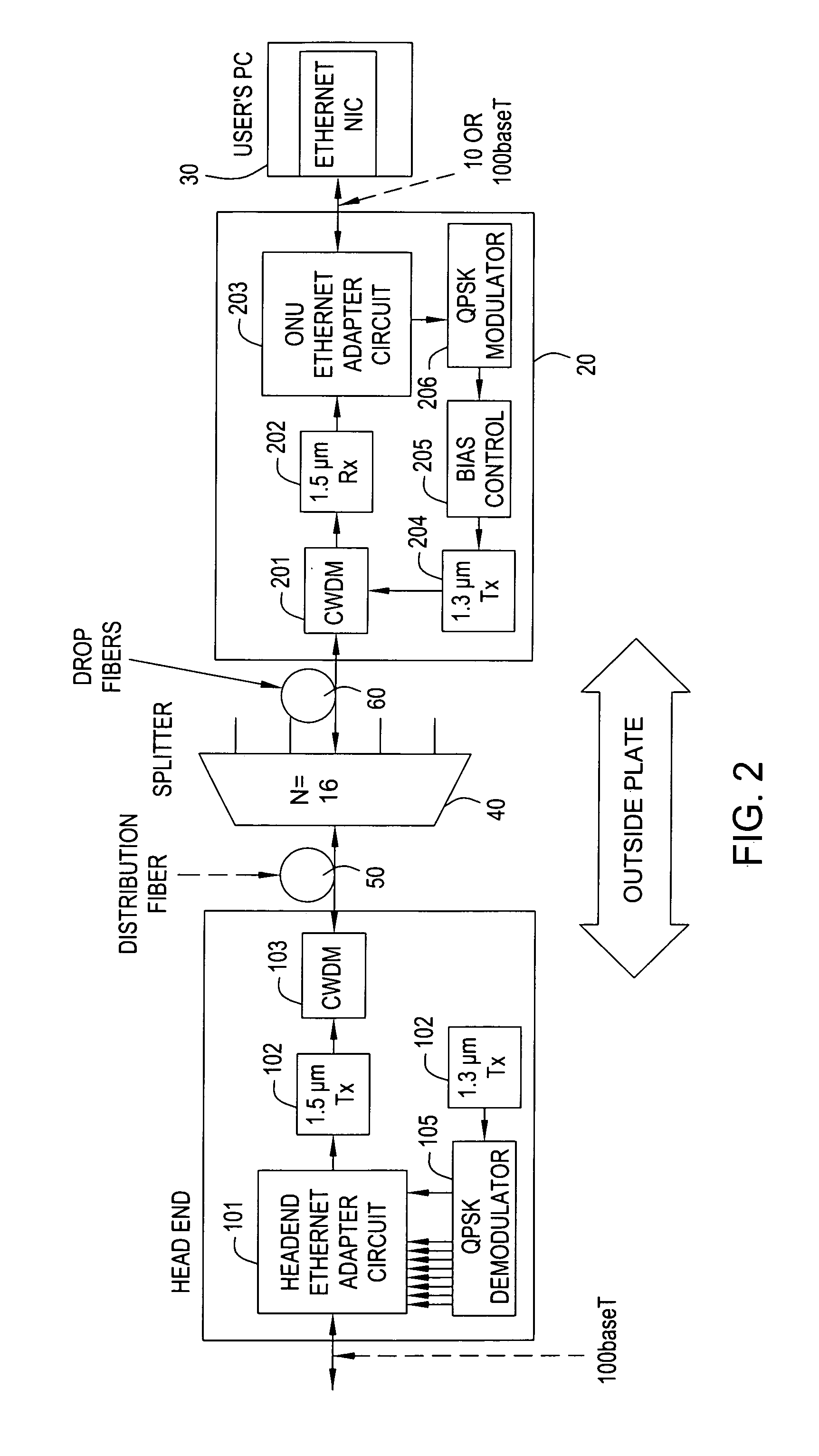
[0019]FIG. 2 shows an exemplary embodiment of a data communications system in accordance with the present invention.

[0020]In the exemplary system of FIG. 2, the head-end 10 comprises a Headend Ethernet adapter circuit 101 which is connected via a 100-baseT connection, for example, to a data network (not shown) of a service provider. The data network may be connected, in turn, to the Internet, for example, since a likely application of this network is to provide Internet access. The Headend Ethernet adapter circuit 101 passes the downstream 100-baseT signal to a 1.5 μm transmitter (Tx) 102. In addition, the adapter circuit 101 combines a plurality of upstream signals provided by a QPSK demodulator 105 (which generates one ˜10 Mb / s signal for each upstream channel) into a single 100-baseT signal for connection to the head-end data network. Some buffering may be needed in the adapter circuit 101 to avoid losing packets in the process of combining the upstream channels.

[0021]The output ...


PUM


Abstract

A data communications system which provides multiple logical channels on a passive optical network (PON) using subcarrier multiple access (SCMA). The PON includes multiple optical network units (ONU) which each communicate with a head-end over a logical channel. Collisions among upstream transmissions are thereby avoided and high speed Ethernet service over large distances is made possible.

Description

FIELD OF THE INVENTION[0001]The present invention relates to data communications networks, particularly Ethernet data networks.BACKGROUND INFORMATION[0002]Ethernet was designed for office environments, where distances between users (and distances between users and networking hubs) are relatively short (˜100 meters). Ethernet relies on a shared-bus architecture which is not particularly suited to applications where distances between users are substantially longer, such as in residential applications. In residential applications, a service provider such as a telephone company or an MSO (CATV service provider) might want to have its active equipment located in a central office or hub, which could be up to 20 km from subscribers.[0003]When considering Fiber-To-The-Home (FTTH) or Fiber-to-the-Curb (FTTC) systems, one approach has been a type of network called a Passive Optical Network (PON). A general review of PONs can be found in an article by David W. Faulkner, et al. “Optical Network...

Claims


Application Information

Patent Timeline
IPC IPC(8): H04J14/00
CPCH04J14/0226H04J14/0282H04J14/0252H04J14/0247H04Q11/0067H04J3/1694H04Q11/0071
Inventor WOOD, THOMAS HUNTINGTON
Owner WSOU INVESTMENTS LLC
Why Eureka
Try Eureka