
Deflectable tip catheter with guidewire tracking mechanism

Inactive Publication Date: 2006-08-08
ATRIONIX
View PDF47 Cites 216 Cited by
  • Summary
  • Abstract
  • Description
  • Claims
  • Application Information

AI Technical Summary

Benefits of technology

[0025]The deflectable tip catheter of the present invention provides the physician with the ability to aim the distal end of the guidewire in a desired direction as the guidewire is advanced from the distal end of the catheter. By using the deflectable tip portion to help direct the advancement of the guidewire, the physician's ability to maneuver the guidewire (and therefore the catheter) around sharp angles is dramatically improved. The deflectable tip catheter also can be used in other conventional modes as well. Such as, for example, the deflectable tip portion can be deflected to help steer the catheter through the patient's vasculature or to reduce resistance as the catheter is advanced over bends in the guidewire. Preferably, the deflectable tip catheter is designed for use with a variety of commercially available cardiology guidewires.
[0027]An elongated catheter body extends from the handle portion to the deflectable tip portion. The elongated catheter body is formed with an inner catheter, a stainless steel braid, and an outer extrusion. The inner catheter is preferably formed with a plurality of lumens including a guidewire lumen, a pull wire lumen, an inflation lumen, a co-axial cable lumen, and a thermocouple lead lumen. The elongated catheter body is relatively stiff as compared with the deflectable tip portion. The elongated catheter body is also constructed to provide high fidelity torque transmission to the deflectable tip portion when torque is applied to the handle portion.

Problems solved by technology

Abnormal patterns of electrical conduction in the heart can produce abnormalities in the cardiac cycle known as arrythmias.
A common form of arrhythmia, known as atrial fibrillation, is a pervasive problem in modem society.
Atrial fibrillation is associated with an increased risk of myocardial ischemia, especially during strenuous activity, and has also been linked to congestive heart failure, stroke, and other thromboembolic events.
Unfortunately, the highly invasive nature of such procedures may be prohibitive in many cases.
Such arrhythmias are generally not amenable to localized ablation techniques because the excitation waves may circumnavigate a focal lesion.
While the disclosures above describe feasible catheter designs for imparting linear ablation tracks, as a practical matter, most of these catheter assemblies have been difficult to position and maintain placement and contact pressure long enough and in a sufficiently precise manner in the beating heart to successfully form segmented linear lesions along a chamber wall.
Indeed, many of the aforementioned methods have generally failed to produce closed transmural lesions, thus leaving the opportunity for the reentrant circuits to reappear in the gaps remaining between point or drag ablations.
However, the use of a guidewire alone does not provide an adequate means for placement of a catheter in a pulmonary vein because placement of the guidewire itself within a pulmonary vein poses a significant challenge.
Although deflectable tip catheters have been successful in addressing certain internal cardiac areas, existing deflectable tip catheter designs are not well-suited for advancing an ablation catheter into a pulmonary vein.
In practice, it has been found that existing deflectable tip catheter designs are not capable of navigating the sharp angle from the fossa ovalis to the pulmonary vein without great difficulty.
Furthermore, once the deflectable tip catheter reaches the pulmonary vein ostium, the ablation element is often unable to sustain sufficient contact with the surrounding tissue to create an adequate circumferential lesion.

Method used


Image

  • Deflectable tip catheter with guidewire tracking mechanism
  • Deflectable tip catheter with guidewire tracking mechanism
  • Deflectable tip catheter with guidewire tracking mechanism

Examples


Embodiment Construction

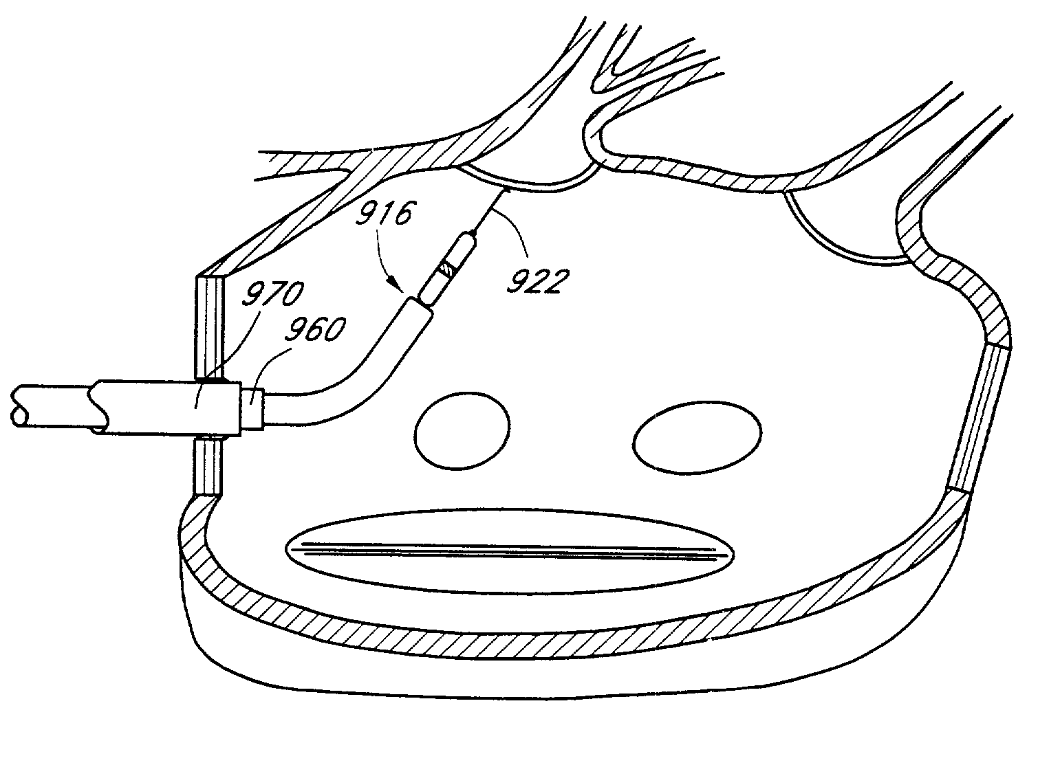
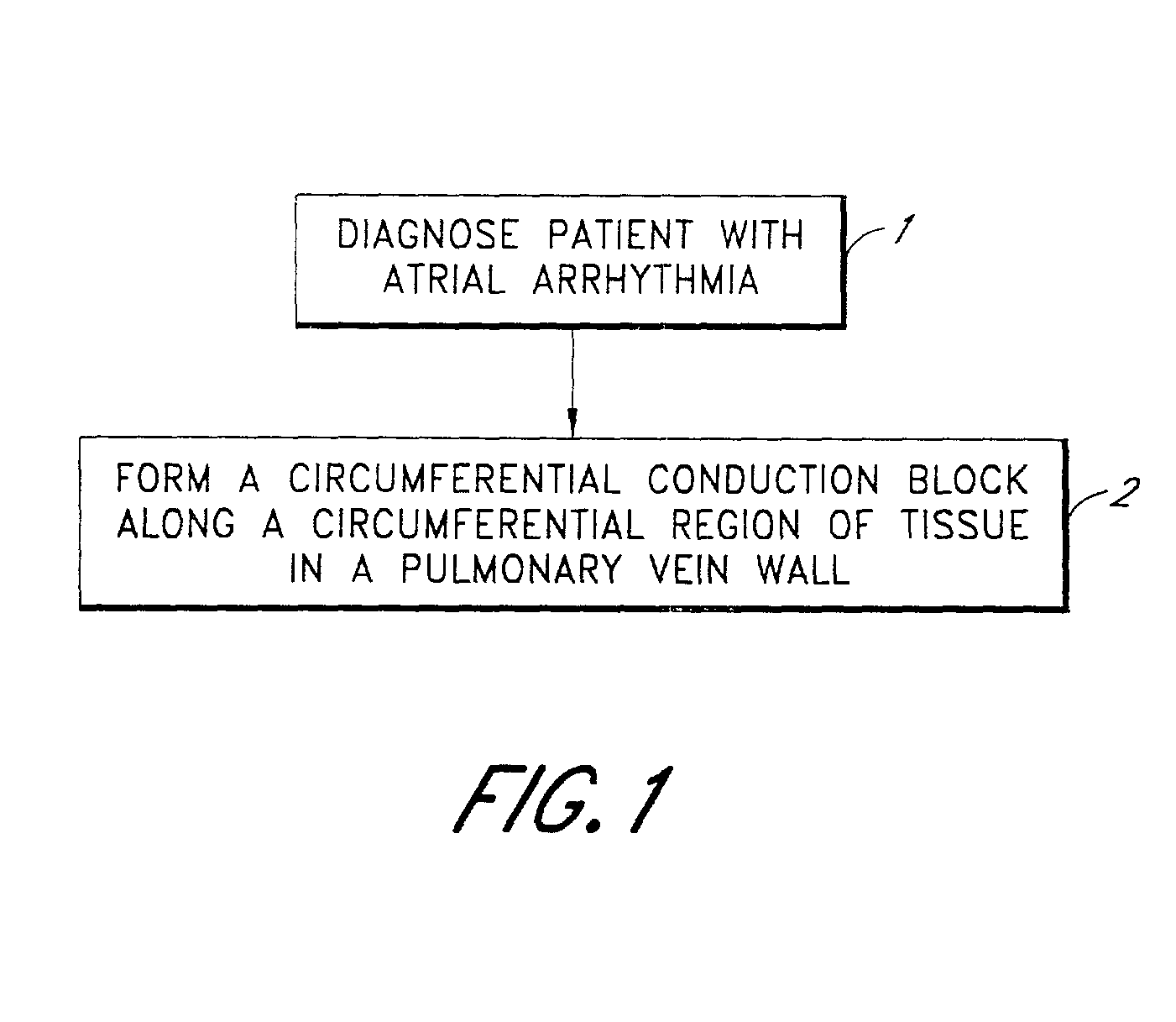
[0082]The present invention relates to an improved deflectable tip catheter that works in combination with a guidewire to facilitate the advancement of a catheter through a patient's vasculature. This invention has a wide variety of applications in the area of catheter-based therapies, however, for illustrative purposes, the invention is described with respect to the treatment of atrial fibrillation whereby a circumferential ablation catheter is advanced into a pulmonary vein ostium. Particular embodiments for pulmonary vein isolation are shown and described by reference to FIGS. 1–18B, with the related method of treatment broadly illustrated in diagrammatical form in the flow diagram of FIG. 1. The deflectable tip catheter assembly of the present invention and its method of operation are shown and described by reference to FIGS. 19–28.

[0083]The following terms will have the following meanings throughout this specification.

[0084]The terms “body space,” including derivatives thereof,...


PUM


Abstract

A deflectable tip catheter that is used in combination with a guidewire for delivery of an ablation element to target areas of a patient's vasculature. The deflectable tip catheter has a handle portion, an elongated shaft and a deflectable tip portion. A guidewire lumen extends through the elongated shaft and deflectable tip portion. A guidewire passes through the guidewire lumen and exits from a port in the distal end of the deflectable tip portion. The deflectable tip of the catheter is deflected by manipulation of the handle portion to direct the advancement of the guidewire as the guidewire is advanced out of the distal port. By using the deflectable tip portion to direct the advancement of the guidewire, the physician's ability to navigate sharp angles is greatly improved. The deflectable tip catheter is particularly suitable for delivering an ablation element to a pulmonary vein or pulmonary vein branch for performing circumferential ultrasound vein ablation to treat atrial fibrillation.

Description

RELATED APPLICATIONS[0001]The present application claims priority under 35 U.S.C. §119(e) to U.S. Provisional Application No. 60 / 205009, filed May 16, 2000.TECHNICAL FIELD[0002]The present invention relates to a medical device for positioning a therapeutic device in a body structure. More particularly, the invention relates to a deflectable tip catheter that functions in combination with a guidewire to facilitate the advancement of a circumferential ablation device into a pulmonary vein ostium.BACKGROUND OF THE INVENTION[0003]Abnormal patterns of electrical conduction in the heart can produce abnormalities in the cardiac cycle known as arrythmias. A common form of arrhythmia, known as atrial fibrillation, is a pervasive problem in modem society. Atrial fibrillation is associated with an increased risk of myocardial ischemia, especially during strenuous activity, and has also been linked to congestive heart failure, stroke, and other thromboembolic events.[0004]In the human heart, no...

Claims


Application Information

Patent Timeline
IPC IPC(8): A61F2/00A61B18/00A61B17/00A61B17/22A61B18/14A61F2/958A61M25/00A61M25/01
CPCA61B17/2202A61B18/1492A61B19/54A61B2017/00292A61B2018/00083A61B2018/00095A61B2018/00238A61B2018/00285A61B2018/00375A61B2018/00898A61M25/0108A61N7/02A61B2018/00214A61B90/39
Inventor LESH, MICHAEL D.ROSS, MICHAEL R.PEAKCOCK, III, JAMES CTAYLOR, KEVIN J.
Owner ATRIONIX
Learn More