Long range optical reader

Inactive Publication Date: 2006-08-15
HAND HELD PRODS
View PDF266 Cites 111 Cited by
  • Summary
  • Abstract
  • Description
  • Claims
  • Application Information

AI Technical Summary

Benefits of technology

[0009]In a further aspect of the invention, the reader's illumination system can be adapted so that a signal strength of image signals generated at long range reading distances is enhanced.

Problems solved by technology

Unfortunately, problems have been noted with presently available laser scan engine based long range optical readers.
At long range reading distances, scanning lines projected by a laser scan engine are difficult to read, making it difficult to lo

Method used


Image

  • Long range optical reader
  • Long range optical reader
  • Long range optical reader

Examples


Embodiment Construction

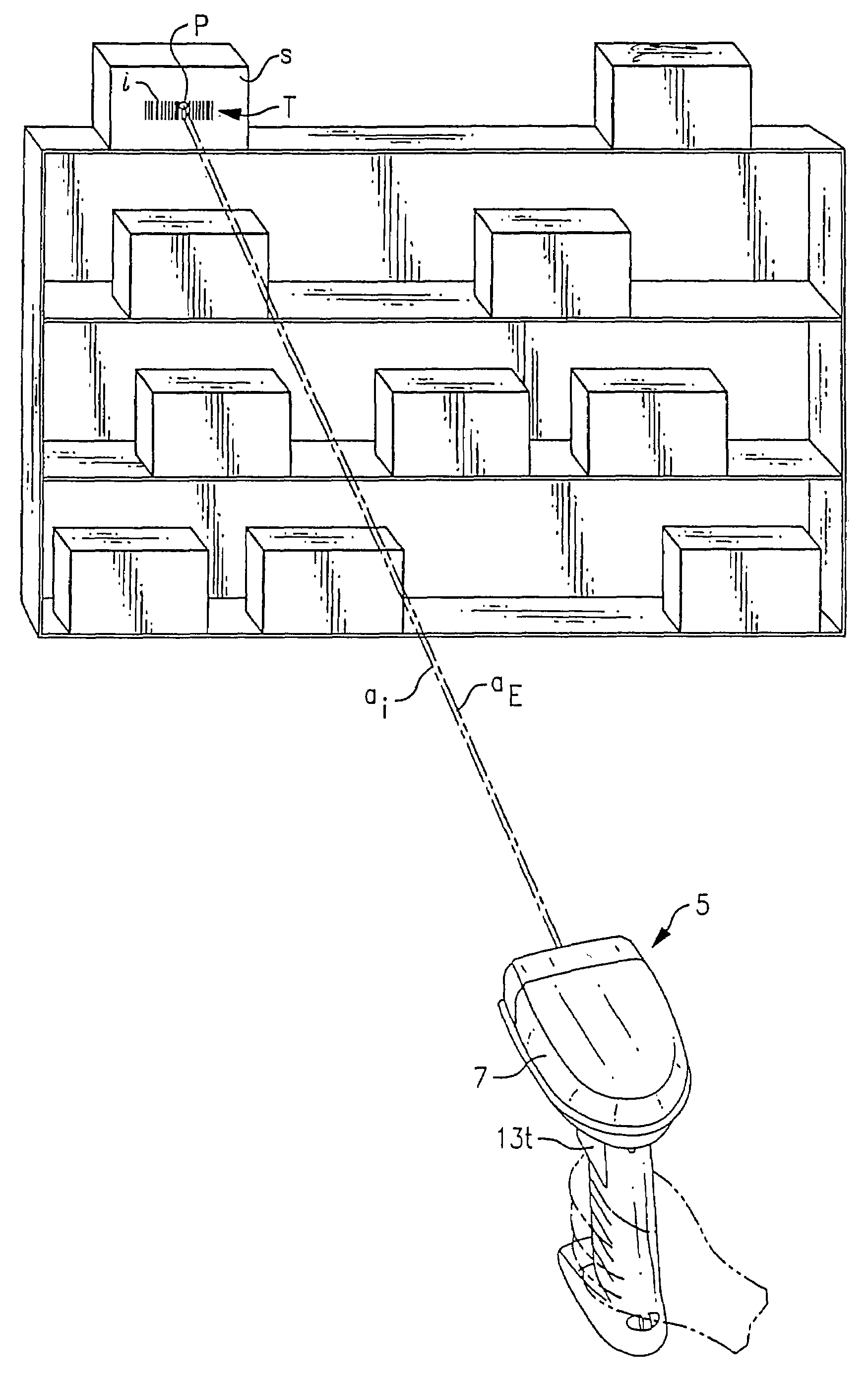
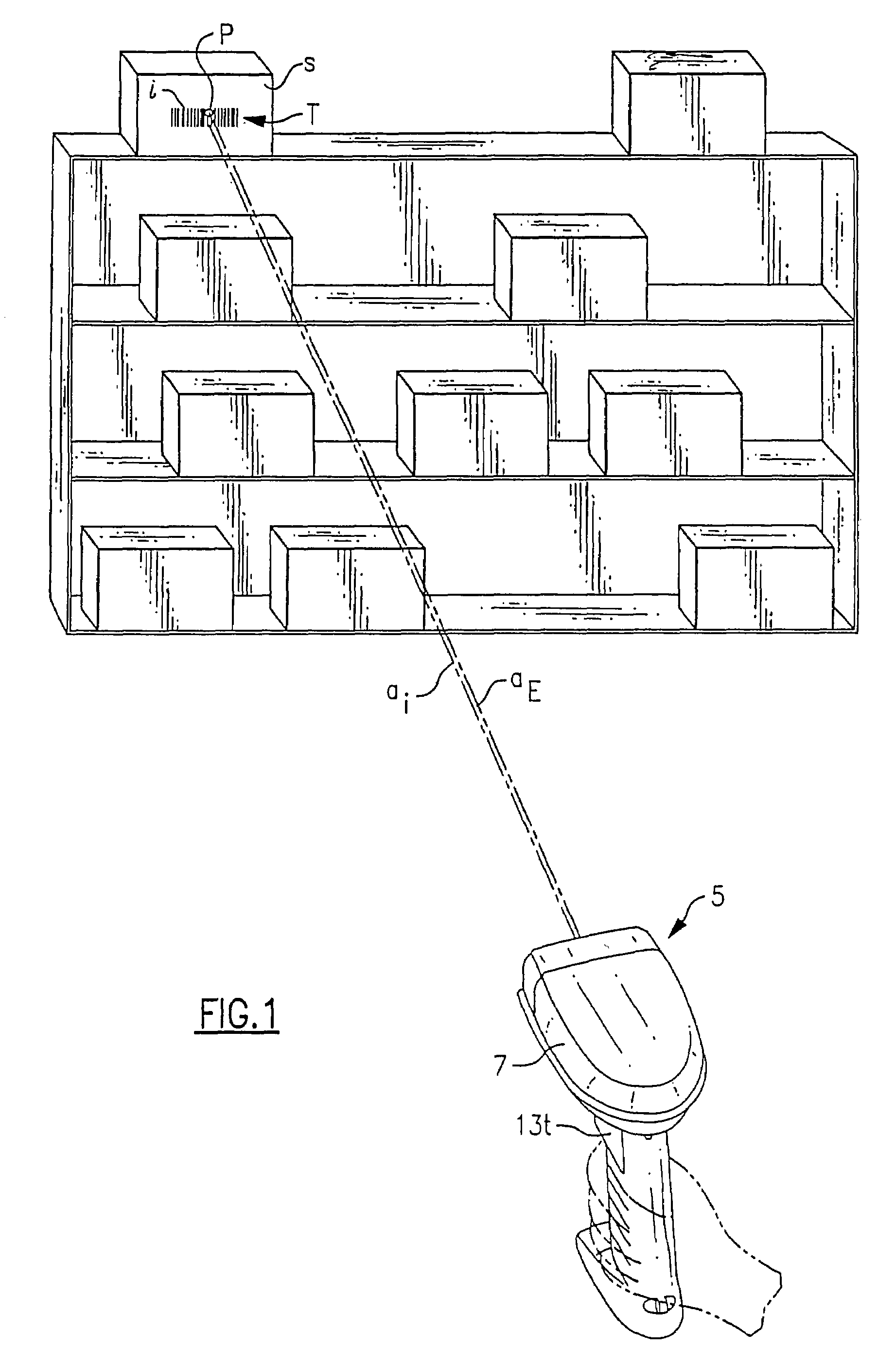
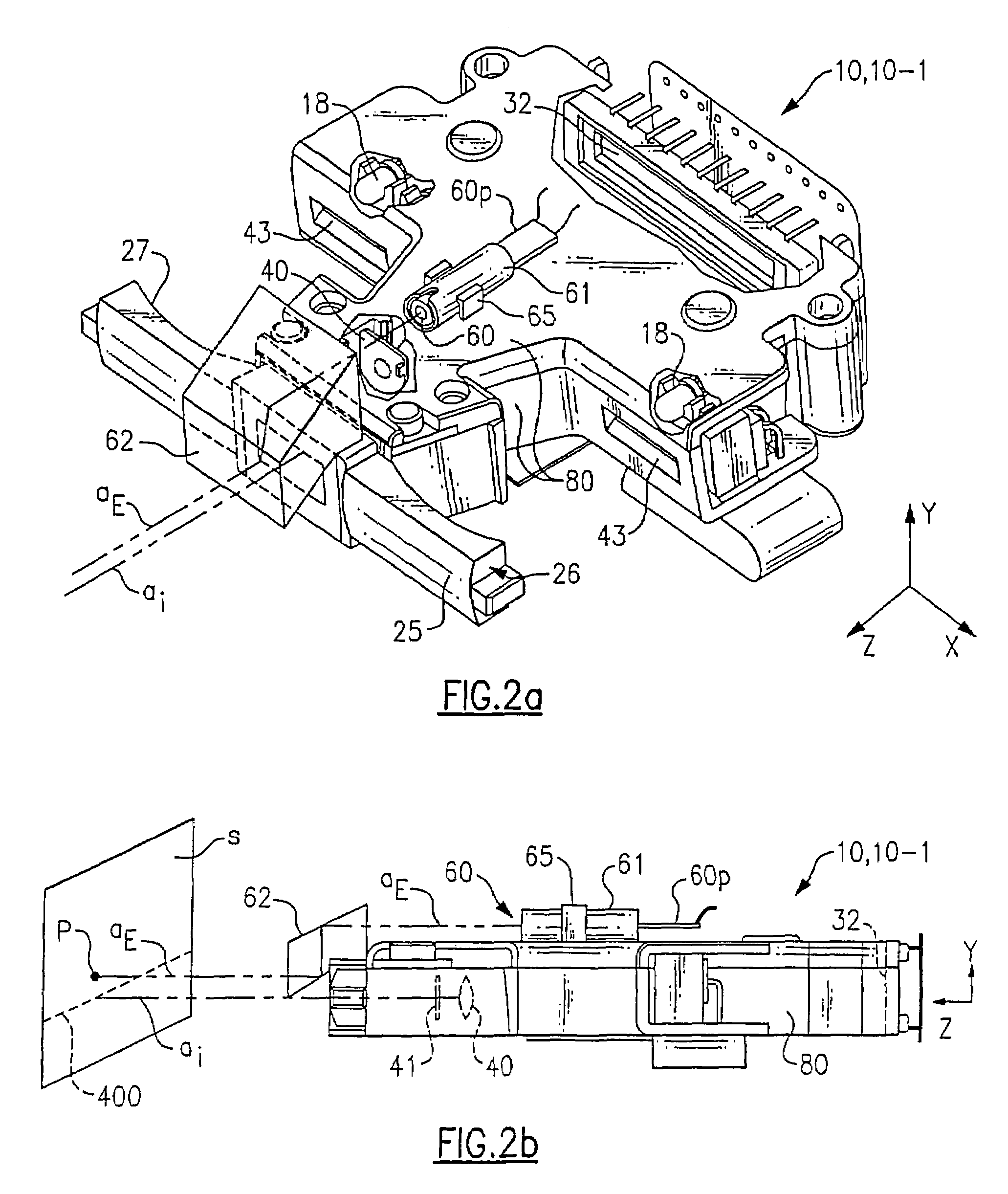
[0063]An optical reader of the invention in use in an industrial application is shown in FIG. 1. Reader 5 is adapted for reading at very long range reading distances, e.g., such as five feet or more. Typically, reader 5 is employed to read standard or “retro-reflective” bar codes. Retro-reflective bar codes, common in warehouse and factory applications, are formed on highly reflective surfaces such that a majority of incident light is reflected back to reader 5. As will be explained in greater detail herein, reader 5 includes imaging optics 40 (as seen, e.g., in FIGS. 2b and 2e) which configure reader 5 so that reader 5 has a long range best-focus distance (e.g., more than 5 feet).Further, long range reader 5 typically includes a long range targeting assembly which is adapted so that a visible aiming pattern P (see FIGS. 7a–7h) is projected within or proximate a target, T, at a long reader-to-target distance. The term “target,” T, herein refers to the space on an indicia-bearing sub...


PUM


Abstract

An optical reader in one embodiment can include a substrate defining an opening and solder pads coupled to the substrate proximate the opening. A laser diode including first, second, and third electrical leads can also be coupled to the substrate. First, second and third solder pads can be provided on the substrate and the first, second, and third electrical leads of the laser diode can be coupled to the first, second, and third solder pads. An optical reader in another embodiment can include a substrate having a first surface and a second surface. A laser diode assembly configured to emit a laser beam can be coupled to the first surface and an illumination assembly that can include light emitting diodes can be coupled to the second surface.

Description

CROSS REFERENCE TO RELATED APPLICATIONS[0001]This application is a continuation-in-part of, and claims priority to under 35 U.S.C. §120 of, U.S. patent application Ser. No. 10 / 252,484, filed Sep. 23, 2002, which claims the priority, under 35 U.S.C. § 119(e), of U.S. Provisional Application Ser. No. 60 / 387,842 filed Jun. 11, 2002, entitled “Long Range Optical Reader”, both of which are incorporated herein by reference in their entirety.FIELD OF THE INVENTION[0002]The invention relates to optical readers in general and particularly to optical readers adapted for long range reading of decodable indicia.BACKGROUND OF THE INVENTION[0003]Bar codes and other decodable indicia are finding increased use including in industrial applications wherein bar codes are to be read at long range reading distances such as beyond five feet. Presently available optical readers configured for such long range reading are laser scan engine based. In a laser scan engine based optical reader, a laser beam is ...

Claims


Application Information

Patent Timeline
IPC IPC(8): G06K7/10G06K7/14H05K1/11H05K1/18H05K3/24
CPCG06K7/10584G06K7/10722G06K7/10801G06K7/10861G06K7/14H05K1/116H05K2201/10121H05K3/244H05K2201/09072H05K2201/09463H05K2201/0949H05K2201/09645H05K2201/09809H05K1/18
Inventor HAVENS, WILLIAM H.HENNICK, ROBERT J.IZZO, JOHNROBINSON, MICHAEL
Owner HAND HELD PRODS
Why Eureka
Try Eureka