System and method for a transparent color image display utilizing fluorescence conversion of nano particles and molecules

a fluorescence conversion and nano-particle technology, applied in the field of displays, can solve the problems of introducing safety hazards for viewers, limiting the practical applicability of research work, and using multiple lasers as excitation sources

Active Publication Date: 2006-08-15
SUN INNOVATIONS
View PDF70 Cites 175 Cited by
  • Summary
  • Abstract
  • Description
  • Claims
  • Application Information

AI Technical Summary

Benefits of technology

[0011]To display multiple colors on the screen, fluorescent molecules or nano-particles of different emitting wavelengths are deposited on the displaying screen or dissolved in the screen; multiple excitation light sources of different wavelengths may be combined and illuminated on the screen. Composite displaying colors are obtained through the mixing of three basic fluorescent emitting colors. Molecules or nano-particles with different fluorescent colors are either premixed and deposited as a single layer; or are deposited as a multiple-layered structure on the displaying screen. These molecules and nano-particles are so small that they will not scatter the visible light and block the view through the transparent screen.

Problems solved by technology

In both situations, the display screens are opaque and people can only see the information on the display surface but cannot see through the screens.
The major drawback for both methods is the use of multiple lasers as the excitation sources.
The use of multiple lasers is normally required for the up-conversion process due to the inefficiency of the process.
The use of very intense, infrared lasers substantially limits the practical applicability of the research works and may introduce safety hazards for the viewers.

Method used


Image

  • System and method for a transparent color image display utilizing fluorescence conversion of nano particles and molecules
  • System and method for a transparent color image display utilizing fluorescence conversion of nano particles and molecules
  • System and method for a transparent color image display utilizing fluorescence conversion of nano particles and molecules

Examples


Embodiment Construction

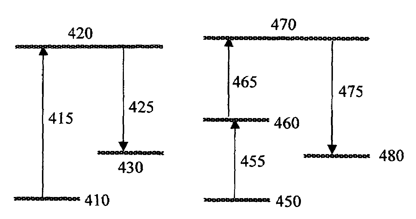
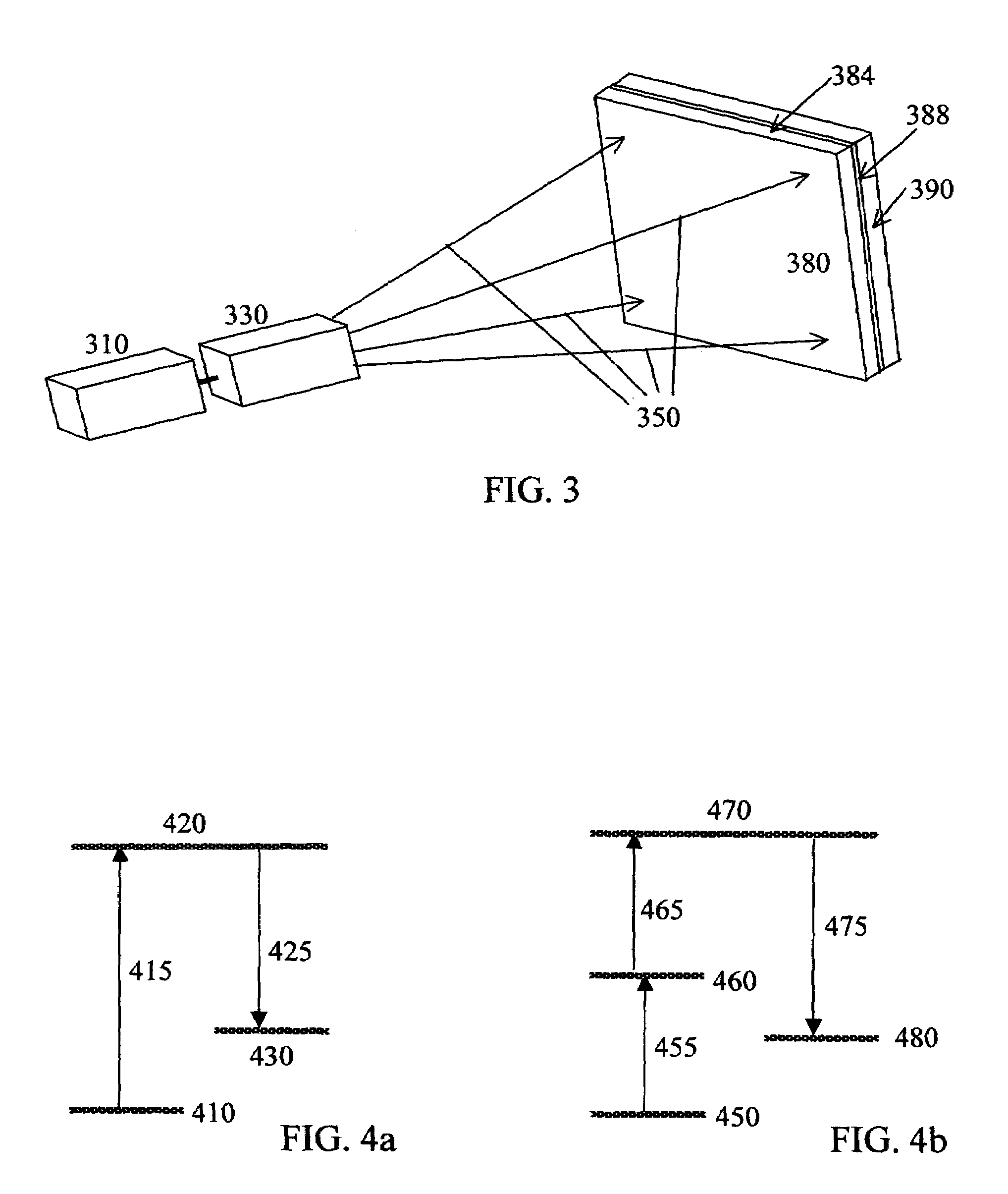
[0021]The present invention discloses an improved system and method, materials and designs of a transparent image display that utilizes fluorescence conversion (FC) process. The improved display system disclosed herein consists of an excitation light source, a transparent display screen containing fluorescent molecules or nano-particles, photo-acoustic light beam steering mechanisms, and a feed back mechanism. Once illuminated, the fluorescent screen converts the invisible (or less visible) excitation lights into red, green or blue emissions. Rastering or scanning of the excitation beam according to a predefined or a programmed data generates an image on the fluorescent screen.

[0022]The first preferred embodiment of the present invention is illustrated in FIG. 3. A radiation source 310 delivers an intense, collimated beam of invisible (or less visible) radiation. The radiation beam passes an optical image processor 330 and the modified radiation beam 350 is projected on to a FC disp...


PUM

PropertyMeasurementUnit
wavelength rangeaaaaaaaaaa

Abstract

A system and a method of a transparent color image display utilizing fluorescence conversion (FC) of nano-particles and molecules are disclosed. In one preferred embodiment, a color image display system consists of a light source equipped with two-dimensional scanning hardware and a FC display screen board. The FC display screen board consists of a transparent fluorescence display layer, a wavelength filtering coating, and an absorption substrate. In another preferred embodiment, two mechanisms of light excitation are utilized. One of the excitation mechanisms is up-conversion where excitation light wavelength is longer than fluorescence wavelength. The second mechanism is down-conversion where excitation wavelength is shorter than fluorescence wavelength. A host of preferred fluorescence materials for the FC screen are also disclosed. These materials fall into four categories: inorganic nanometer sized phosphors; organic molecules and dyes; semiconductor based nano particles; and organometallic molecules. These molecules or nano-particles are incorporated in the screen in such a way that allows the visible transparency of the screen. Additionally, a preferred fast light scanning system is disclosed. The preferred scanning system consists of dual-axes acousto-optic light deflector, signal processing and control circuits equipped with a close-loop image feedback to maintain position accuracy and pointing stability of the excitation beam.

Description

[0001]This application claims priority to the provisional application entitled “Advanced laser fluorescent displays”, Ser. No. 60 / 471,968, filed by the same subject inventors and assignee as the subject invention on May 19, 2003.BACKGROUND OF THE INVENTION[0002]1. Field of the Invention[0003]The present invention relates generally to displays and more particularly to a system and a method for two-dimensional transparent displays utilizing special laser induced fluorescence media.[0004]2. Background Art[0005]Image display and associated technologies are a fundamental necessity of today's society. Application areas include communication, entertainment, military, medical and health. Traditionally, a display system consists of a source beam, beam masks or deflectors, and a projection screen. Although the basic concept of a display system served us well in the past, new technologies have been developed steadily. As demonstrated in FIG. 1, a prior art light beam based display system consi...

Claims


Application Information

Patent Timeline
Patent Type & Authority Patents(United States)
IPC IPC(8): G03B21/14C09K11/08G02F2/02H01J31/48H04N9/31
CPCC09K11/08H04N9/3129G02F2/02
Inventor LIU, JIANQIANGSUN, XIAO-DONG
Owner SUN INNOVATIONS
Why Eureka
Try Eureka