Surgical milling instrument for shaping a bone cavity

Inactive Publication Date: 2006-08-15
MEDICINELODGE
View PDF20 Cites 108 Cited by
  • Summary
  • Abstract
  • Description
  • Claims
  • Application Information

AI Technical Summary

Benefits of technology

[0016]Embodiments of this invention provide a bone milling instrument that is capable of accurately and precisely milling complex three-dimensional surfaces. This is accomplished by providing the surgeon with a bone milling instrument that guides a milling tool along a path predetermined by a template that is specific to a prosthesis geometry. The milling tool removes the bone tissue necessary to provide an optimal fit between the bone and the implant.
[0017]Embodiments of this invention provide a milling instrument that allows the surgeon to prepare a cavity that will mate with the external geometry a customized modular prosthesis. This is done by providing a series of interchangeable adjustable templates designed to guide the cutting instrument in a path that relates to the shape of a particular modular femoral prosthesis construct.
[0019]As implants, instrumentation and surgical techniques improve, the size of the incision and the invasiveness of the procedure necessary to accomplish a THA lessens. Hence, embodiments of this invention provide instrumentation that can be adapted for use in minimally invasive THA surgery. This is accomplished by providing minimally sized instruments that function through a minimally invasive incision and by providing instrumentation that is designed to only cut the tissue necessary for optimal cavity preparation.
[0022]The guide body has a distal section dimensioned to fit into a bore in bone. Templates, which are unique to the proposed cavity shape, are attached to the guide body. Three-dimensional and two-dimensional guide surfaces on the templates help guide the mill in the desired path to cut a cavity in the bone that is unique to the template guide surface shape.

Problems solved by technology

As is inevitable with a finite selection of sizes to fit the infinitely variable anatomic structures of the human skeletal system, surgeons were typically forced to compromise their fit by selecting a prosthesis size that was either too large or too small or simply did not have the right shape to fit the patient optimally.
Since this micro-motion could eventually lead to loosening of the prosthesis, resulting in pain, instability and ultimately failure of the fixation, it is important to create the bone cavity so that it closely matches the implant.
Due to the variety of implant shapes that can be constructed with modular femoral prostheses, and the complexity of the anatomy of the proximal femur, it is generally not practical to precisely prepare a cavity to accept the prosthesis with conventional bone removal instrumentation.
However, only contacting the implant in this area may result in a compromised fixation, unable to adequately prevent excessive relative micro-motion over the life of the implant.
This technique works for implants with a simple geometry, but does not work well for those with more complex curved surfaces.
Such conventional bone removal techniques are typically not adequate to prepare the cavity for the more complex geometries associated with modular prostheses.
The removal of too much tissue results in a mating surface with gaps that do not allow bone-to-implant apposition.
The removal of too little tissue results in an improperly seated implant.
When bone removal instruments such as broaches are used to remove relatively bulky segments of bone tissue, the resulting surface texture of the cavity is often too course for intimate implant-to-bone contact.

Method used


Image

  • Surgical milling instrument for shaping a bone cavity
  • Surgical milling instrument for shaping a bone cavity
  • Surgical milling instrument for shaping a bone cavity

Examples


first embodiment

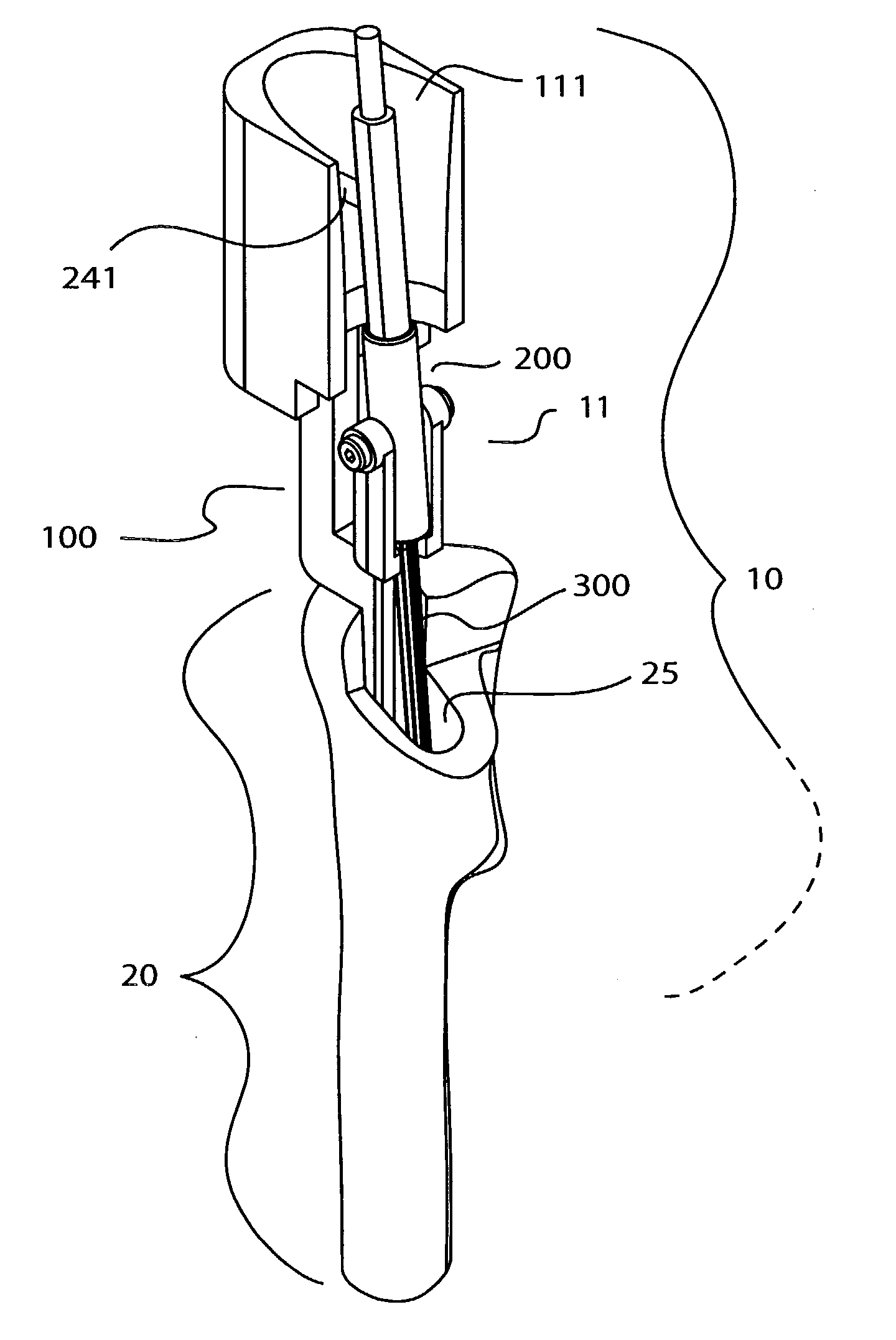
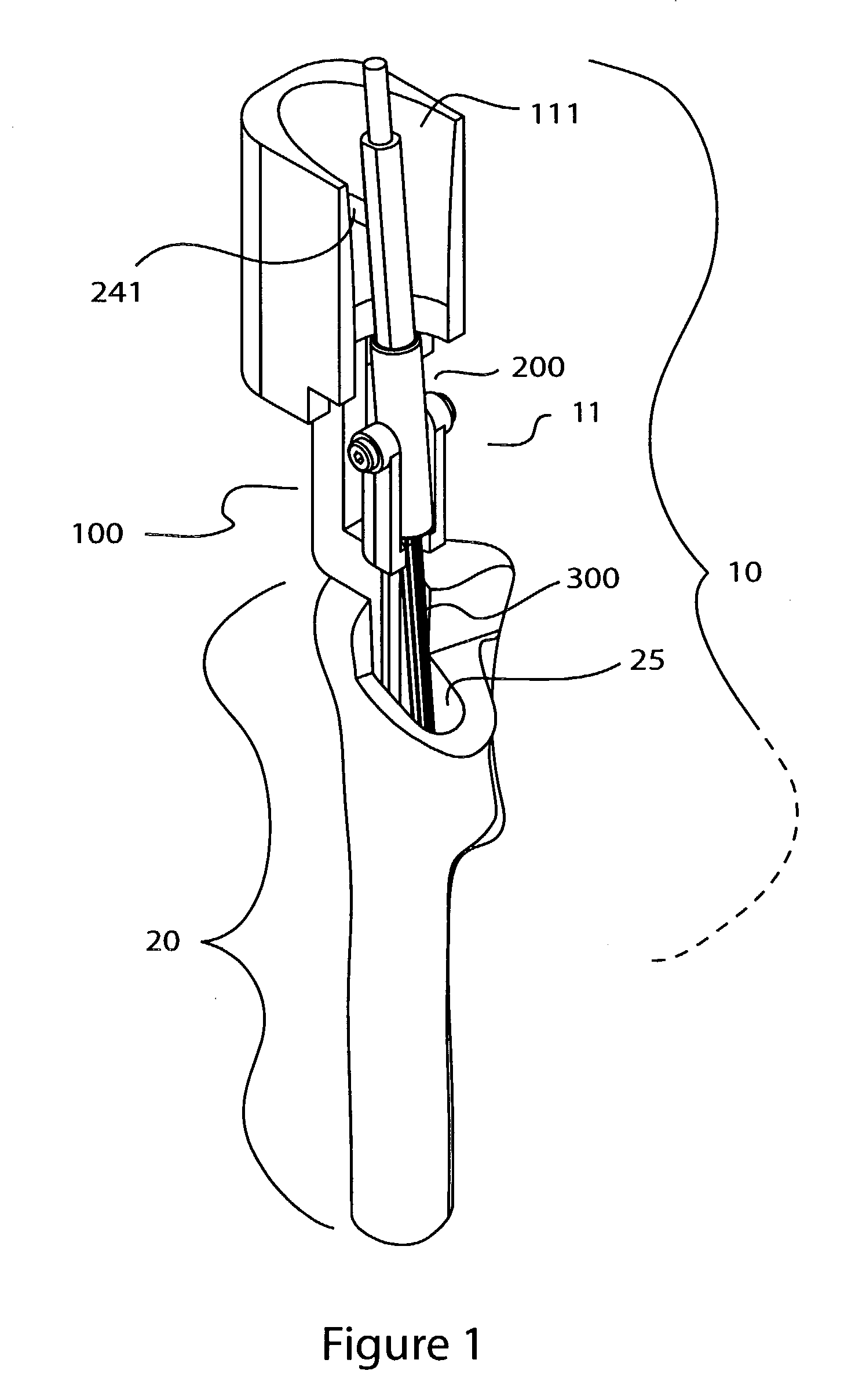
[0046]Looking first at FIG. 1, a milling instrument assembly 10 for shaping a bone cavity 25 in a proximal femur 20 is shown. In FIG. 1, the milling instrument assembly 10 is positioned to prepare the cavity 25 in the proximal femur 20. The milling instrument assembly 10 comprises three major subassemblies that are shown in greater detail in FIG. 2. These subassemblies are: a guide body 100, a mill guide 200, and a tissue cutting mill 300.

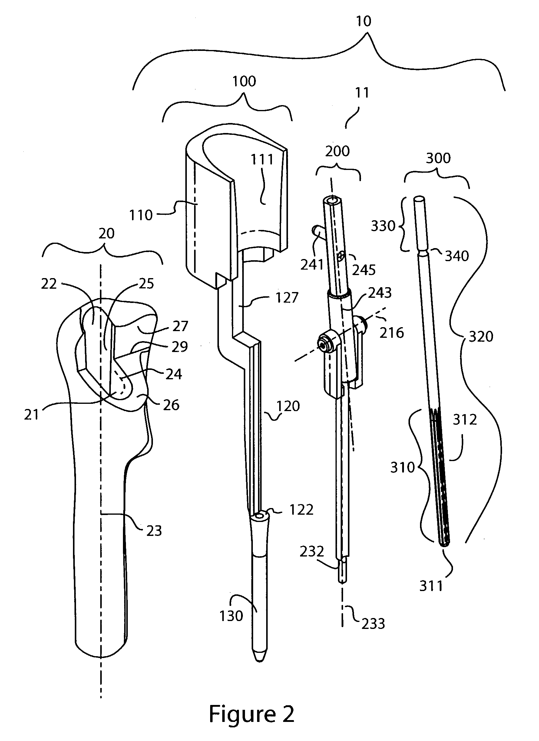
[0047]In FIG. 2, these three subassemblies are shown before assembly and before insertion into the proximal femur 20. As shown in FIG. 2, prior to insertion of the milling instrument assembly 10, some of the tissue is removed from the proximal femur 20 to allow for insertion of the milling instrument assembly 10. During a THA procedure, a surgeon typically removes the diseased femoral head tissue by cutting transverse 26 and longitudinal 27 osteotomy cuts in the bone that intercept along an osteotomy edge 29. The surgeon also drills a bore 22 dista...

second embodiment

[0075]the milling instrument assembly 15 of FIGS. 6, 7, 8 works in conjunction with the circular mill guide 500 shown in FIG. 7. The mill guide 500 essentially works as a universal joint between mill 300 and guide body 100. When a non-axial force is applied to the mill 300, this force is constrained by the circular mill guide 500 to an orientation that is both pivoting along the pivot guide axis 216 and rotating along the mill guide axis 243.

[0076]A handle 590 is shown in FIG. 6 that can be rigidly attached to the follower 240 of either of the above described mill guide 200 or the circular mill guide 500. This handle 590 is generally comprised of a guidance section 293 that facilitates the gripping and guidance by the hand of a surgeon (not shown) and a connection portion 594 that mounts to the follower 240. The guidance section 293 has a grip portion 591 positioned along the longitudinal shaft of the guidance section 293. This grip portion 591 is used for gripping or making contact...

fourth embodiment

[0083]In the milling instrument assembly 13 shown in FIG. 13 and FIG. 14, the template section 1110 is axially adjustable with respect to the tongue 1171 and groove 1160 sliding axis by a thumb screw 1170. The thumb screw 1170 is allowed to rotate along its axis, but is axially captured in translation in the tongue 1171. The male helical threads 1174 on this thumb screw 1170 mate with truncated female helical threads 1170 in the groove 1160. The template section 1110 is thus adjusted axially by rotating the thumb screw 1174.

[0084]Other types of adjustable connections in which the longitudinal position of the template section 1110 is adjusted with respect to the guide body frame 1120 can be used. These adjustable connections include those commonly used in mechanical fastening, such as cam locks, rack and pinion connections and meshing gear mechanism connections.


PUM


Abstract

A mill guide instrument for guiding a tissue cutting tool is provided that is made up of subassemblies of a guide body and a mill guide. The guide body has a distal section dimensioned to fit into a bore in bone and a removable template with a guide surface unique to a proposed cavity shape. The mill guide is connected to the guide body and provides for controlled relative motion between the mill and the guide body. The mill guide has an attached stylus that follows the guide surface of the template. The stylus follows the template guide surface so as to constrain the path of the mill to a preferred milling path.

Description

CROSS-REFERENCE TO RELATED APPLICATIONS[0001]This patent application claims benefit of pending prior U.S. Provisional Patent Application Ser. No. 60 / 356,945, filed Feb. 12, 2002 by T. Wade Fallin et al. for SURGICAL MILLING INSTRUMENT FOR SHAPING A BONE CAVITY, which patent application is hereby incorporated herein by reference.BACKGROUND OF THE INVENTION[0002]As the external shapes of orthopedic surgical implants become more complex,-correspondingly sophisticated instruments are needed to prepare bone tissue to receive these implants. One such example are the instruments required to prepare the proximal femur for a total hip arthroplasty (THA) prosthesis. Other implant procedures such as total knee arthroplasty and total shoulder arthroplasty also require similar tissue preparation with milling instruments that replicate the three-dimensional geometry of the prosthesis surface.[0003]The majority of THA implants in use today consist of three main components: the acetabular cup prost...

Claims


Application Information

Patent Timeline
IPC IPC(8): A61B17/00A61F5/00A61B17/17
CPCA61B17/175
Inventor FALLIN, T. WADEGERBEC, DANIEL E.PEPPER, JOHN R.
Owner MEDICINELODGE
Why Eureka
Try Eureka