Magnetic thrust motor

a thrust motor and magneto-driven technology, applied in the direction of motor/generator/converter stopper, motor/generator control, windings, etc., can solve the problems of unsatisfactory mounting requirements, complex prior systems, and requiring too many components, so as to facilitate relative movement and reduce connections

Inactive Publication Date: 2006-08-15
PACIFIC BEARING
View PDF10 Cites 17 Cited by
  • Summary
  • Abstract
  • Description
  • Claims
  • Application Information

AI Technical Summary

Benefits of technology

[0005]One aspect of the present invention is directed toward a motor that uses magnetic propulsion for generating movement along a travel path in which the motor controller is mounted onboard the thrust block, thereby reducing connections the need for a remote motor controller. The motor includes a thrust rod extending along a travel path. The thrust rod includes an array of magnets arranged along the travel path arranged to create magnetic fields for generating magnetic propulsion. The motor also includes a thrust block comprising a mounting body, electrical coils, and the onboard motor controller. The mounting body of the thrust block is arranged adjacent the thrust rod with the electrical coils and the motor controller being mounted thereto. The electrical coils are in electrical communication with the thrust rod, such that energizing the electrical coils facilitates relative movement between the thrust block and the thrust rod along the travel path.
[0008]Further aspects of the present invention are directed toward a servo linear motor that uses magnetic propulsion for generating movement along a travel path that includes an encoder scale directly mounted to the surface of the rail. It is an advantage that this can increase accuracy and also eliminate the need for separate plates or other structure used for mounting the scale. Also, electrical energy may be transmitted to the motor carriage if desired through the rail (e.g. through an electrical contact line along the rail or through the material of rail or a portion thereof), thereby allowing the linear motor to be wireless if desired.

Problems solved by technology

Heretofore, there have been too many deficiencies with thrust tube motors to allow them to effectively compete or provide a commercially practical alternative to screw type servo motors.
These prior systems are often too complex, require too many components, have undesirable mounting requirements and are too expensive to effectively compete in the marketplace for many machine applications, despite several technological advantages that thrust tube motors or modules provide over screw type servo motors.

Method used


Image

  • Magnetic thrust motor
  • Magnetic thrust motor
  • Magnetic thrust motor

Examples


Embodiment Construction

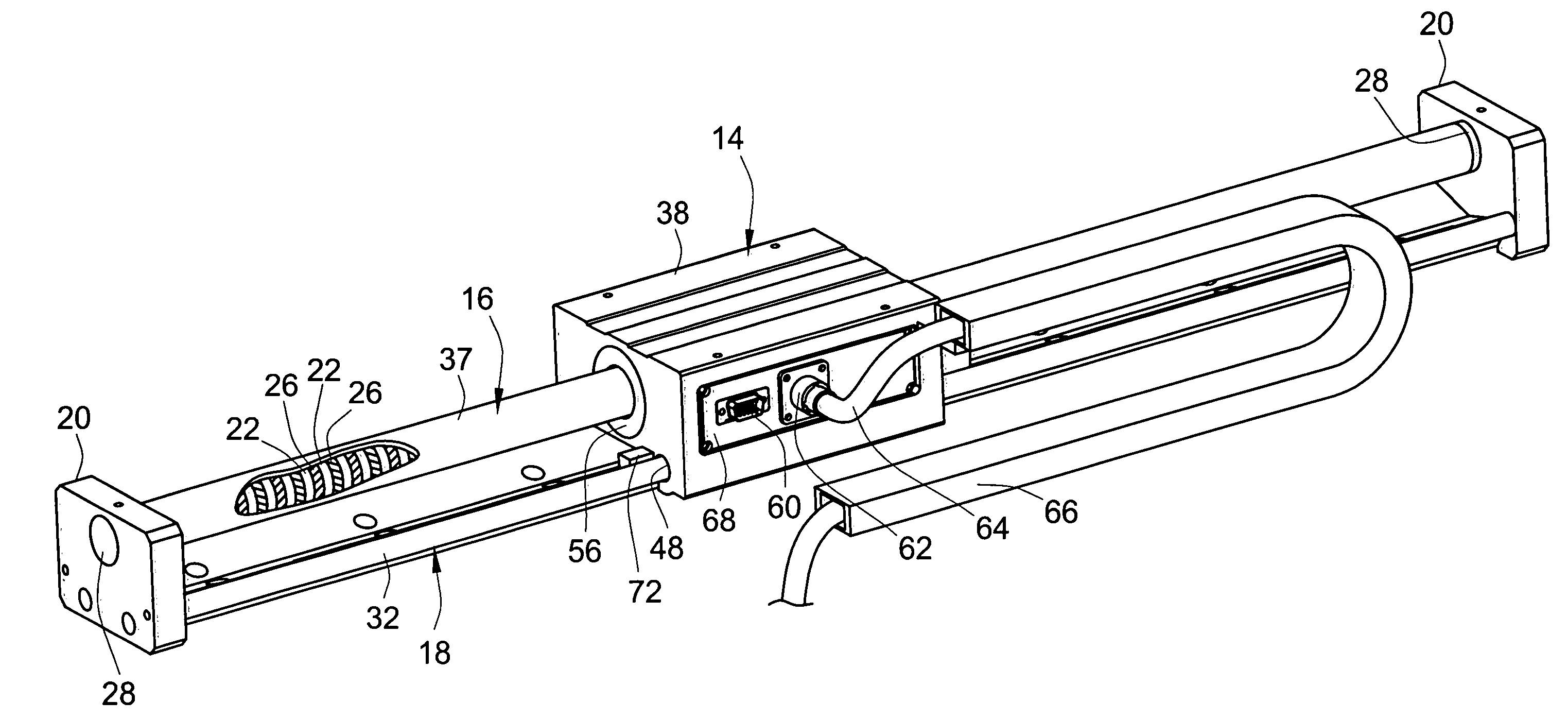
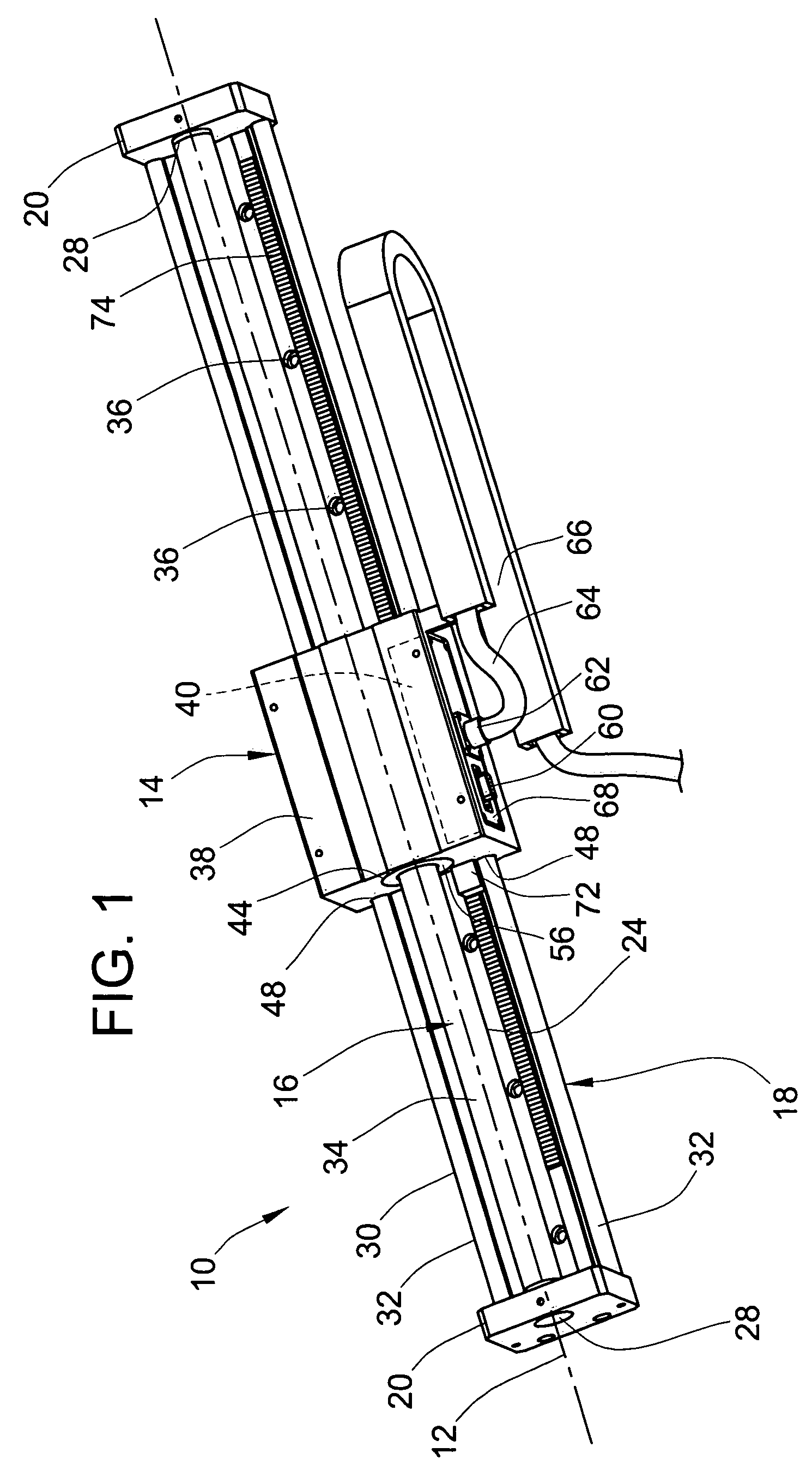
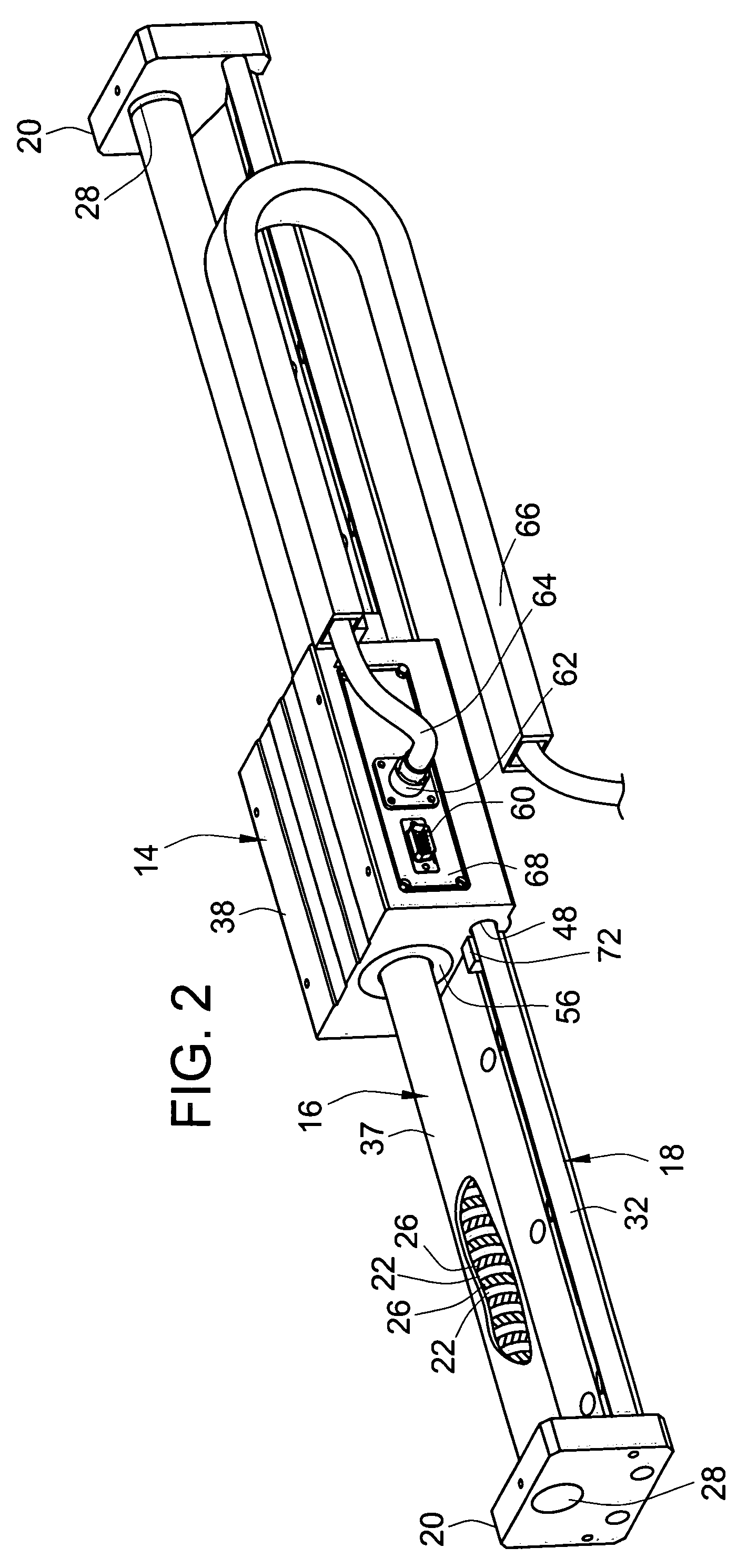
[0019]An embodiment of the present invention is illustrated in FIGS. 1, 2, and 5 as a servo motor 10 that uses magnetic propulsion for facilitating movement along a travel path 12. The servo motor 10 is shown as the linear type with movement along a linear travel path although other travel path shapes are possible. As shown, the motor 10 may be provided as a complete linear motion package to include a thrust block or carriage 14, a thrust rod 16, a bearing rail 18, and a pair of end supports 20.

[0020]As illustrated in FIG. 5, the thrust rod 16 includes a plurality of permanent magnets 22 that are arranged in a linear array in a hollow support tube 24, which may be comprised of steel material. The permanent magnets 22 are contained in the bore of the hollow support tube and are aligned linearly along the linear travel path 10 in a linear succession, with the poles of adjacent magnets 22 being reversed (e.g. N-S, S-N, N-S, S-N, etc.), although other magnet arrangements including a sin...


PUM


Abstract

A motor is disclosed that uses magnetic propulsion for generating movement along a travel path in which the motor controller is mounted onboard the thrust block, thereby reducing connections the need for a remote motor controller. The motor includes a thrust rod extending along a travel path. The thrust rod includes an array of magnets arranged along the travel path arranged to create magnetic fields spaced along the travel path for generating magnetic propulsion when electrical coils on the thrust block are energized. The thrust block comprising a mounting body, electrical coils, and the onboard motor controller. The block may integrally provide a bearing surface that slides along a rail that may also provide the mounting structure and main support for the motor. A encoder mounted to the thrust block with a scale mounted directly to guide rail is also provided.

Description

FIELD OF THE INVENTION[0001]This invention pertains to motors, and more specifically to magnetically driven thrust motors often incorporated as linear motor into a linear motion system.BACKGROUND OF THE INVENTION[0002]Linear motion systems for industrial machinery and tooling often employ ball or acme screws driven by a servo motor to facilitate linear motion. The typical arrangement in these systems is that a stationary rotary motor drives a threaded screw that impart rectilinear motion upon a movable carriage that has a threaded nut engaging the screw. The movable carriage is then typically guided by a linear motion system such as one of those systems commercially available from the present assignee, Pacific Bearing Company®, located in Rockford, Ill.[0003]However, there is another type of linear motor which uses magnetic propulsion that is sometimes referred to as a thrust tube motor or a thrust tube module (both of which are referred to herein generically as “motor”). Such thrus...

Claims


Application Information

Patent Timeline
Patent Type & Authority Patents(United States)
IPC IPC(8): H02K41/00H02K41/03H02P1/00
CPCH02K41/031H02K1/185H02K3/525H02K11/0078H02K7/08H02K11/0026H02K11/0073H02K5/225H02K11/22H02K11/33H02K11/35
Inventor SCHROEDER, ROBERTGRONEWOLD, ROBERTKOEHLER, CLEVESTEVENS, RICHARDMICHALSKE, GLEN
Owner PACIFIC BEARING
Why Eureka
Try Eureka