Controller for an RF power amplifier

a controller and power amplifier technology, applied in the direction of gain control, amplifier modification to reduce non-linear distortion, supply voltage varying control, etc., can solve the problem of ininverse relationship of power amplifier efficiency and linearity power amplifier introduces nonlinear components or distortion to the signal, etc., to achieve the effect of reducing power dissipation

Inactive Publication Date: 2006-08-15
LUCENT TECH INC
View PDF23 Cites 95 Cited by
  • Summary
  • Abstract
  • Description
  • Claims
  • Application Information

AI Technical Summary

Benefits of technology

[0013]A controller of the present invention provides modulated power supply to an amplifier based upon tracking an envelope of an RF signal. For example, the RF envelope signal is sampled with correction values applied to compensate for distortion (i.e., predistortion) and also to provide bias changes to a power supply output. The predistortion correction values are adjusted synchronously with changes to the power supply bias. Thus, power to the amplifier is varied synchronously with the change in the RF envelope power, thereby resulting in a more efficient amplifier that has lower power dissipation.

Problems solved by technology

Therefore, there is a tradeoff between efficiency and linearity.
If the input signal has an amplitude which causes the power amplifier to operate outside the linear region, the power amplifier introduces nonlinear components or distortion to the signal.
In addition to distorting the signal, the clipping or nonlinear distortion of the input signal, generates spectral regrowth or adjacent channel power (ACP) that can interfere with an adjacent frequency.
Unfortunately, efficiency of the base station amplifier is inversely related to its linearity.
However, peak power is not continuous, and such designs result in inefficient operation of the RF amplifiers.
Typically, strict linearity requirements in modern wireless communication systems dictate the use of the relatively inefficient class A or slight class AB modes.
Naturally, these measures add to the cost, size and weight of the base station equipment.
These very stringent standards have resulted in increased difficulty and complexity in designing efficient RF power amplifiers.
Use of lower rated amplifiers would result in clipping of signals above the highest rated output of the amplifier during those peak power periods and cause interference across communication channels.
However, the total size reduction of such systems, and in particular, the component parts, including specifically RF amplifiers, is limited by the amount of heat dissipated by the RF power stages of the RF amplifiers and the associated power supply design.

Method used


Image

  • Controller for an RF power amplifier
  • Controller for an RF power amplifier
  • Controller for an RF power amplifier

Examples


Embodiment Construction

[0024]The following description of the preferred embodiments is merely exemplary in nature and is in no way intended to limit the invention, its application, or uses. Although the present invention is described in connection with specific component parts operating under specific conditions to control a particular amplifier, it is not so limited, and different or additional component parts may be implemented as part of the invention.

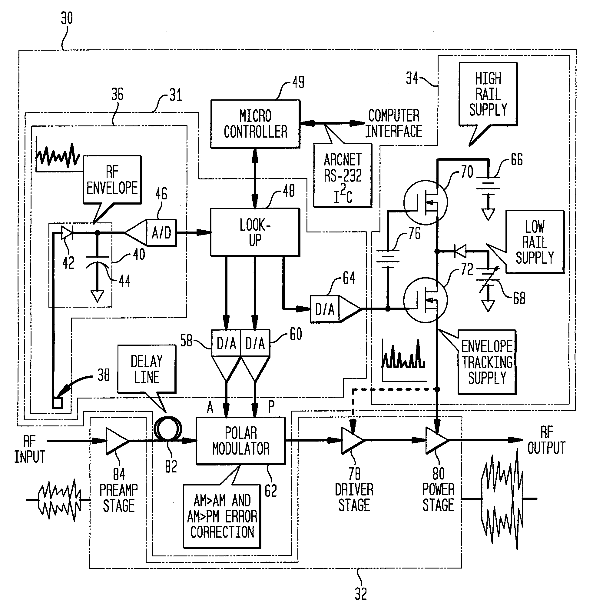
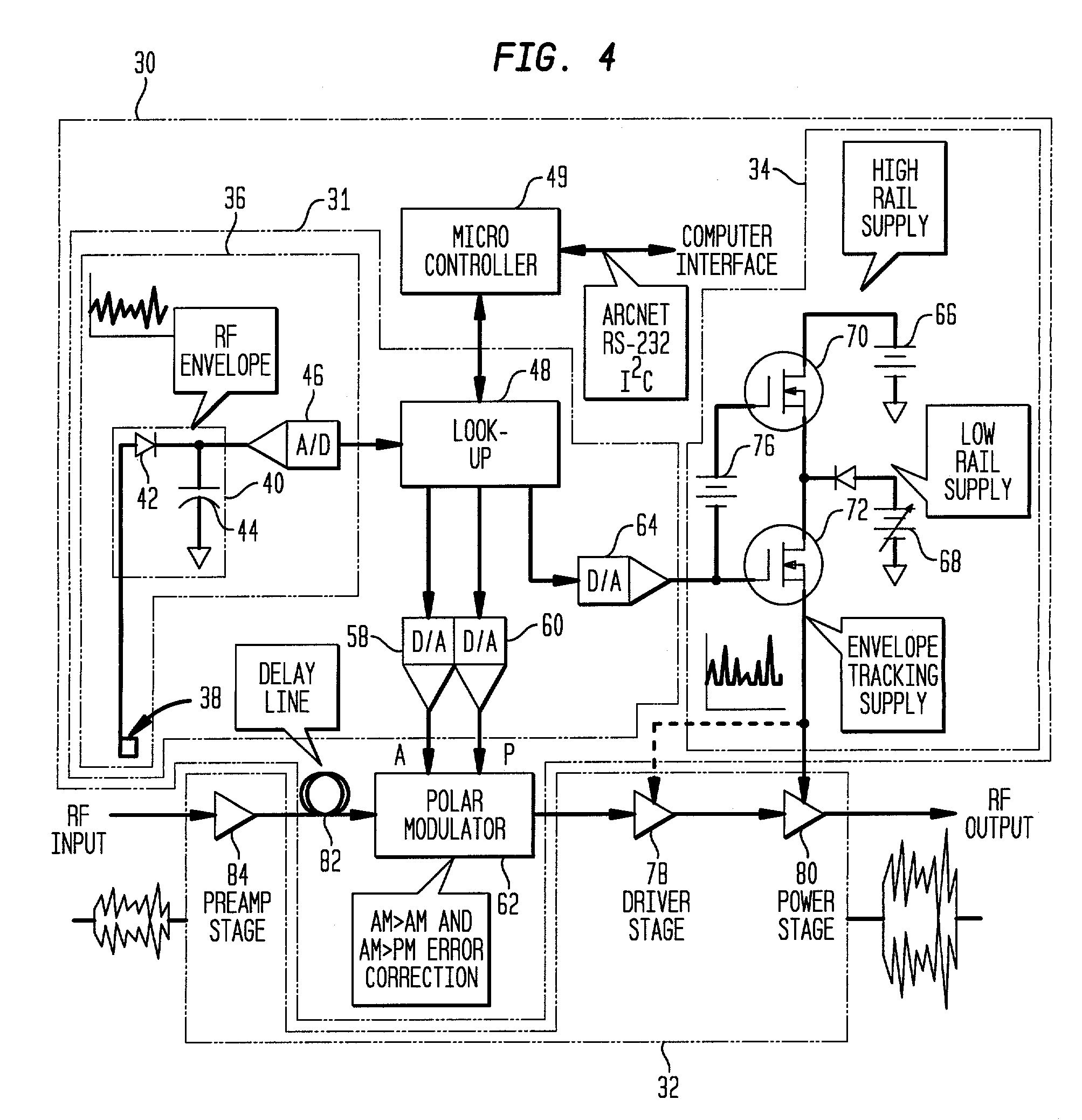
[0025]Generally, the present invention provides a controller for an RF power amplifier to increase its efficiency. Essentially, the power supplied to an RF power stage of the amplifier is modulated as the instantaneous RF envelope power changes. During operation, when the envelope power changes, variations in gain, phase and bias (i.e., direct current (DC) voltage) are compensated for synchronously using a digital look-up table and polar modulation. A type of RF pre-distortion (i.e., linearization) is thereby provided that offsets nonlinear effects and ga...


PUM


Abstract

The controller controls the amplifier and a modulated power supply, supplying power to the amplifier, by detecting an RF envelope of a signal input to the amplifier. Predistortion of the amplifier synchronous with changes of bias is provided using a look-up table. Specifically, amplitude predistortion, phase predistortion and DC voltage level adjustments are made to the RF signal. Adjustments for gain and phase variation are applied synchronously with bias changes.

Description

FIELD OF THE INVENTION[0001]The present invention relates generally to radio frequency (RF) amplifiers.BACKGROUND OF THE INVENTION[0002]Amplifiers produce from an input signal, an output signal having an increased magnitude (i.e., gain). Essentially, an amplifier produces a constant output power at a higher level. Different amplifiers are known and produce various types of gains (e.g., voltage and / or current gain). Amplifiers are rated at a maximum power output for use in different applications. The most efficient output for an amplifier typically occurs when operating at the highest rated output. However, amplifiers are often operated at an average power much lower than the highest rated output in order to achieve a linear output. Therefore, there is a tradeoff between efficiency and linearity.[0003]An ideal power amplifier amplifies an input signal with no waveshape alteration. The ideal power amplifier is therefore characterized as having a transfer function (input signal vs. out...

Claims


Application Information

Patent Timeline
Patent Type & Authority Patents(United States)
IPC IPC(8): H03G3/20H03F1/02H03F1/32H03G3/00
CPCH03F1/0222H03F1/3241H03G3/004H03F1/3282H03F2200/102
Inventor LYNCH, MICHAEL ANTHONY
Owner LUCENT TECH INC
Why Eureka
Try Eureka