
Data access method in the network system and the network system

a network system and data access technology, applied in the field of data access technology, can solve the problems of large latency difference between the local node and the remote node, frequent access between the node devices, poor system performance, etc., and achieve the effect of reducing the latency

Inactive Publication Date: 2006-08-15
NEC CORP
View PDF28 Cites 20 Cited by
  • Summary
  • Abstract
  • Description
  • Claims
  • Application Information

AI Technical Summary

Benefits of technology

[0009]Another object of the present invention is to reduce the latency difference among nodes.
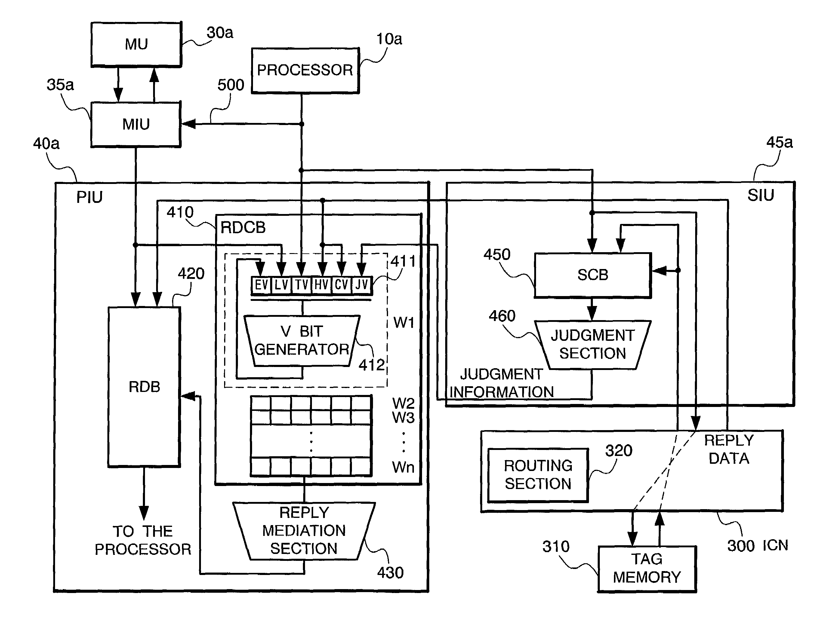
[0014]According to the present invention, a speculative access is made to the memory in the system at the same time as the tag information readout from the tag memory and, based on the tag information read out, whether or not to abolish the data obtained from the memory by the speculative access is decided. This procedure is not like the conventional method with a series of operations where the tag information is read out first and, if the read out tag information shows that the data to be accessed is not stored in the cache memory in the system, the memory access operation is further executed. Instead, the memory access is executed at the same time as the tag information readout and, when the read out tag information shows that the data to be accessed is not stored in the cache memory of the system, the data already obtained by the above access is adopted. Thus, the latency can be reduced.
[0033]In the preferred construction, the data processing means abolishing the speculative readout data when the data found in the cache memory is acquired and sent to the processor in the self node device.

Problems solved by technology

If no restriction is imposed to copying of the data stored in the common memory to the cache memory, however, the data copy having the same address in the common memory may be stored in the cache memories of several processors, which would result in frequent accesses between the node devices.
This spoils the latency of the access to the cache memory or the local memory of the remote node, which leads to a poorer system performance.
Further, since the local memories constituting the common memory are mounted individually one by one for the node devices in this system, the latency difference between the local node and the remote node becomes larger.
This also results in a lower system performance.

Method used


Image

  • Data access method in the network system and the network system
  • Data access method in the network system and the network system
  • Data access method in the network system and the network system

Examples


first operation example

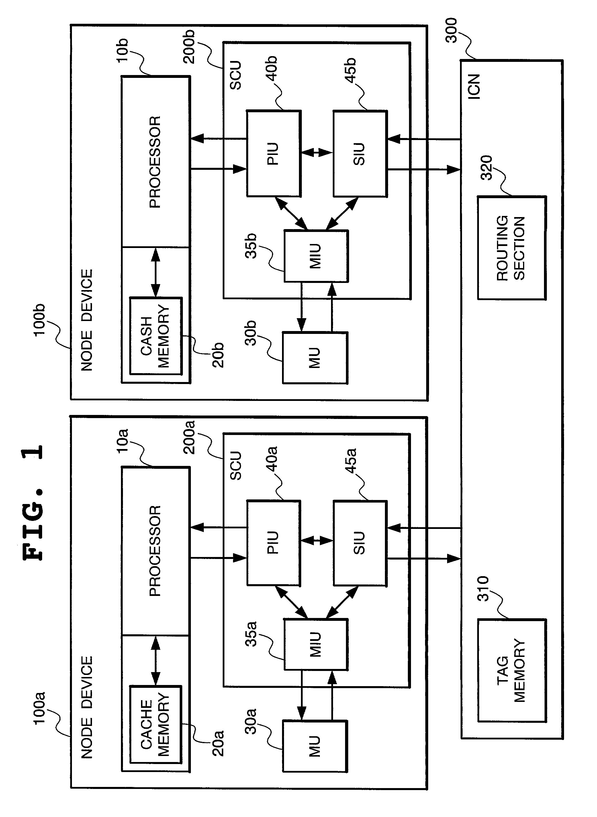
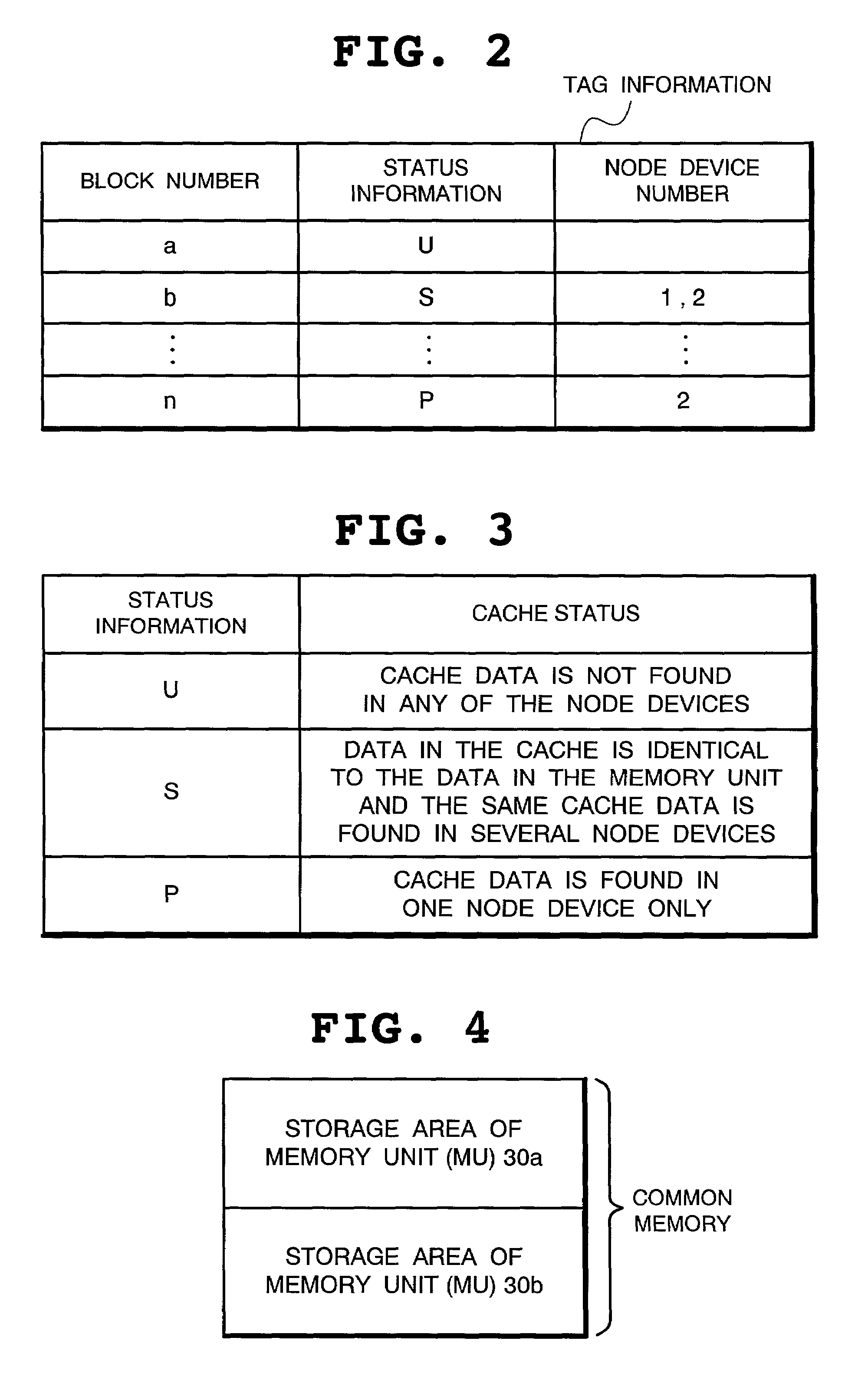
[0087]Next, the operation of the present invention will be described below. First of all, referring to FIG. 11 and other figures, case (1) of FIG. 10 will be described. In this case, the node device 100a serves as the home node and a read type transaction for the local memory (MU 30a) is issued from the processor 10a. Note here that, as shown in FIG. 15, any of the data belonging to the block data with the block No. a stored in the tag memory 310 is subject to readout by the read type transaction.

[0088]Shown at the lower part of FIG. 11 is a time chart illustrating the processing procedure of the operation in this case. As shown in FIG. 11, when the processor 10a of the node device 100a issues a read type transaction, the PIU 40a receives it and, by the routing function to detect the home node of the transaction, finds that the memory unit to be accessed by the transaction is the MU 30a, which is the local memory. The PIU 40a has the SIU 45a conduct the snoop processing for the tag ...

second operation example

[0096]Next, referring to FIG. 12 and other figures, case (2) of FIG. 10 will be described. In this case, the node device 100a serves as the home node and a read type transaction for the local memory (MU 30a) is issued from the processor 10a. Note here that, as shown in FIG. 16, any of the data belonging to the block data with the block No. a stored in the tag memory 310 is subject to readout by the read type transaction and the node device 100b is provided with the node device number “(2)”.

[0097]FIG. 12 shows a time chart illustrating the processing procedure of the operation in this case. As shown in FIG. 12, when the processor 10a of the node device 100a issues a read type transaction, the PIU 40a receives it and, by the routing function to detect the home node of the transaction, finds that the memory unit to be accessed by the transaction is the MU 30a, which is the local memory. The PIU 40a has the SIU 45a conduct the snoop processing for the tag memory 310 and, at the same tim...

third operation example

[0105]Referring now to FIG. 13 and other figures, case (3) of FIG. 10 will be described. In this case, the other node device 100b serves as the home node and a read type transaction for the memory unit (MU 30b) is issued from the processor 10a. Note here that, as shown in FIG. 17, any of the data belonging to the block data with the block No. b stored in the tag memory 310 is subject to readout by the read type transaction.

[0106]FIG. 13 shows a time chart illustrating the processing procedure of the operation in this case. As shown in FIG. 13, when the processor 10a of the node device 100a issues a read type transaction, the PIU 40a receives it and, by the routing function to detect the home node of the transaction, finds that the memory unit to be accessed by the transaction is the MU 30b in the remote node 100b. The PIU 40a has the SIU 45a conduct the snoop processing for the tag memory 310 and, at the same time, sends the control information to the ICN 300 to execute the speculat...


PUM


Abstract

According to this data access method to be used in a network system, while the tag information is read out from the tag memory, the data is speculatively read out from the memory unit in the self node device. When the read out tag information shows that the speculatively read out data is not found in any of the cache memories, such speculatively read out data is sent to the processor in the self node device. When the read out tag information shows that the speculatively read out data is found in one of the cache memories, the data existing in such cache memory is acquired and sent to the processor in the self node device and the speculatively readout data is abolished.

Description

BACKGROUNDS OF THE INVENTION[0001]1. Field of the Invention[0002]The present invention relates to data access technology preferably applicable to a network system, and particularly to a NUMA (Non Uniform Memory Access model) system.[0003]2. Description of the Related Art[0004]FIG. 21 shows a block configuration diagram showing an example of the NUMA system. In this system, each of several node devices 1000a, . . . , 1000n is connected to the other with a bus 1040 so that they can mutually send and receive the required information between them. Each node device has a CPU 1010a ( . . . , 1010n), a local memory 1020a ( . . . , 1020n) and a control unit 1030a ( . . . , 1030n). In addition, as shown in FIG. 22, the local memories 1020a, . . . , 1020n of the node devices constitute a common memory. The CPU 1010a, . . . , 1010n of the node devices are configured so that they can access such common memory.[0005]In the NUMA system as described above, when the CPU 1010a, . . . , 1010n in the ...

Claims


Application Information

Patent Timeline
IPC IPC(8): G06F12/00G06F12/08G06F15/177
CPCG06F12/0813G06F12/0884G06F12/0822G06F2212/2542
Inventor KONDO, HIDETOSHI
Owner NEC CORP
Learn More