Low-jitter clock for test system

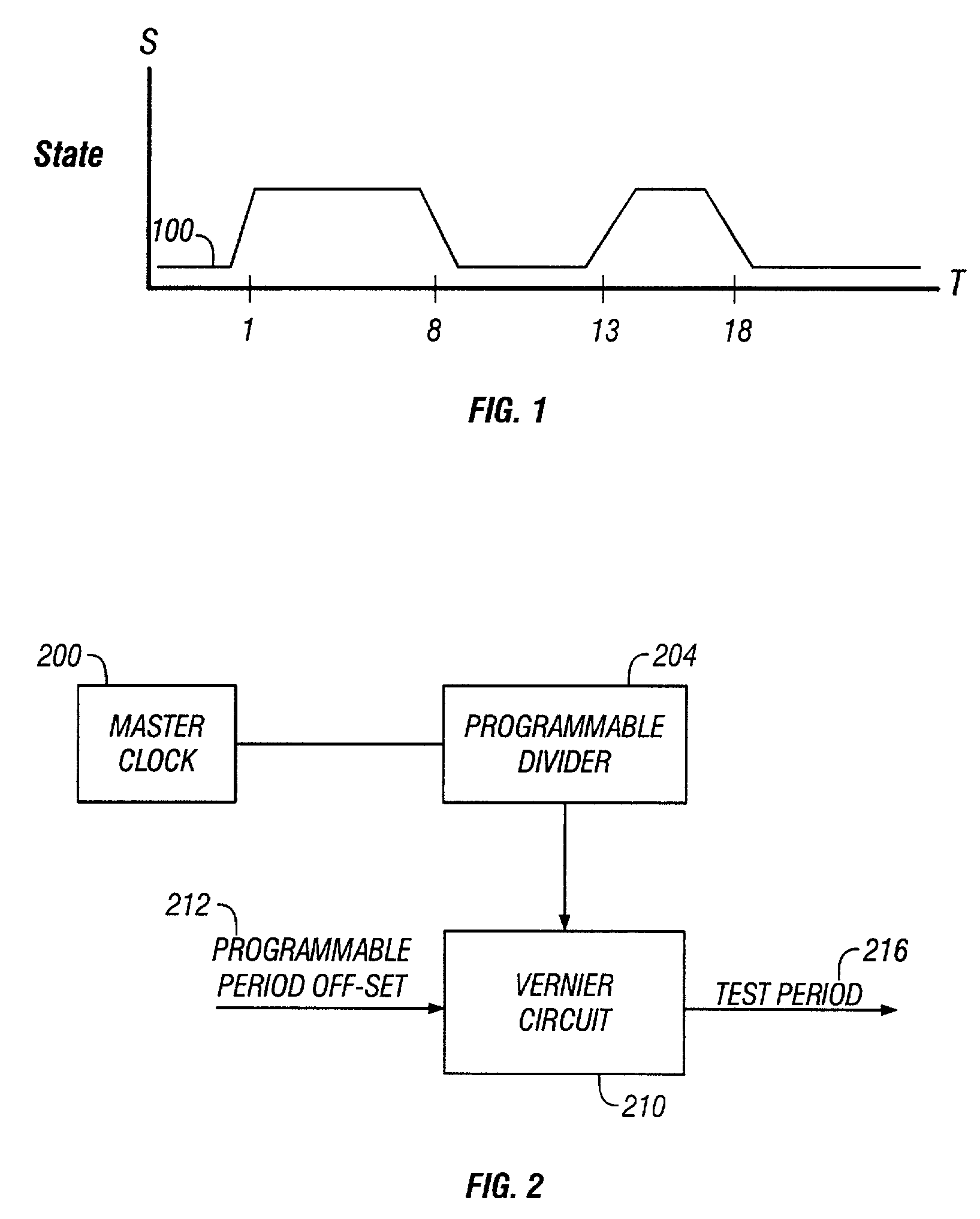
a low-jitter clock and test system technology, applied in the field of low-jitter clocks for test systems, can solve problems such as the problem of period-to-period jitter associated with period vernier based clocks, and achieve the effect of easy movement of the occurren

Inactive Publication Date: 2006-08-15
SCHLUMBERGER TECH CORP
View PDF10 Cites 35 Cited by
  • Summary
  • Abstract
  • Description
  • Claims
  • Application Information

AI Technical Summary

Benefits of technology

[0008]The present inventors recognized that conventional test systems, using a period vernier based clock to generate test pattern signals and clock signals for a DUT, could change clock period instantaneously during run-time, easily move the occurrence of an event within the test period, and provide a clock signal with some period-to-period jitter. The present inventors further recognized that the period-to-period jitter associated with a period vernier based clock can be problematic for certain applications, such as structural testing, that need a low period-to-period jitter clock input to the DUT, in addition to the flexibility of the period vernier based clock for changing the period and moving the occurrence of an event with the period. Consequently, the present inventors developed a low-jitter clock for test systems using period verniers for generating test pattern signals. The present inventors developed the low-jitter clock by using a programmable phase-lock-loop clock that can output a signal that is frequency similar to and phase matched with the generated period vernier based test pattern signals.
[0019]The systems and techniques described here may provide several advantages. For example, one has the ability to produce a clock signal with a dependable placement of edges within that signal, for example, on the order of + / −2 picoseconds (ps) with a master clock period of 2.5 nanoseconds (ns). Moreover, one can generate a clock signal with lower period-to-period jitter (e.g., 2 ps), that will not erode timing margin in applications with a sub-nanosecond internal core clock, which is a significant improvement over conventional systems that can have a period-to-period jitter of about 20 ps. The generated clock signal's stability can result in a stable DUT core clock, an improvement in the timing performance of the DUT, and an increase in the testing yield. As a result, the systems and techniques described here are particularly suited for applications, such as structural testing, that require the flexibility of the period vernier for generating test pattern signals for data pins and the low jitter of the phase-lock-loop clock for clock input.

Problems solved by technology

The present inventors further recognized that the period-to-period jitter associated with a period vernier based clock can be problematic for certain applications, such as structural testing, that need a low period-to-period jitter clock input to the DUT, in addition to the flexibility of the period vernier based clock for changing the period and moving the occurrence of an event with the period.

Method used


Image

  • Low-jitter clock for test system
  • Low-jitter clock for test system
  • Low-jitter clock for test system

Examples


Embodiment Construction

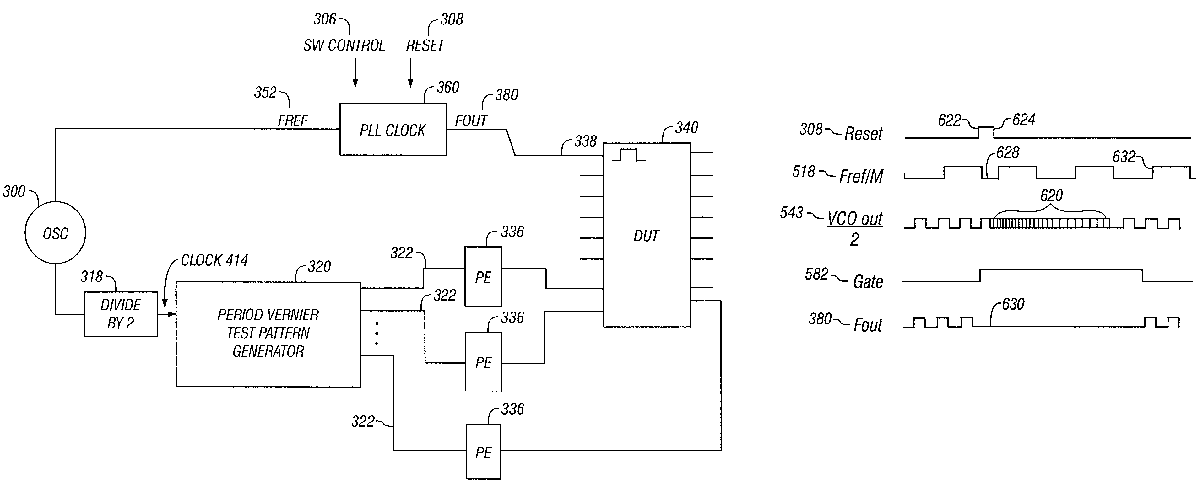
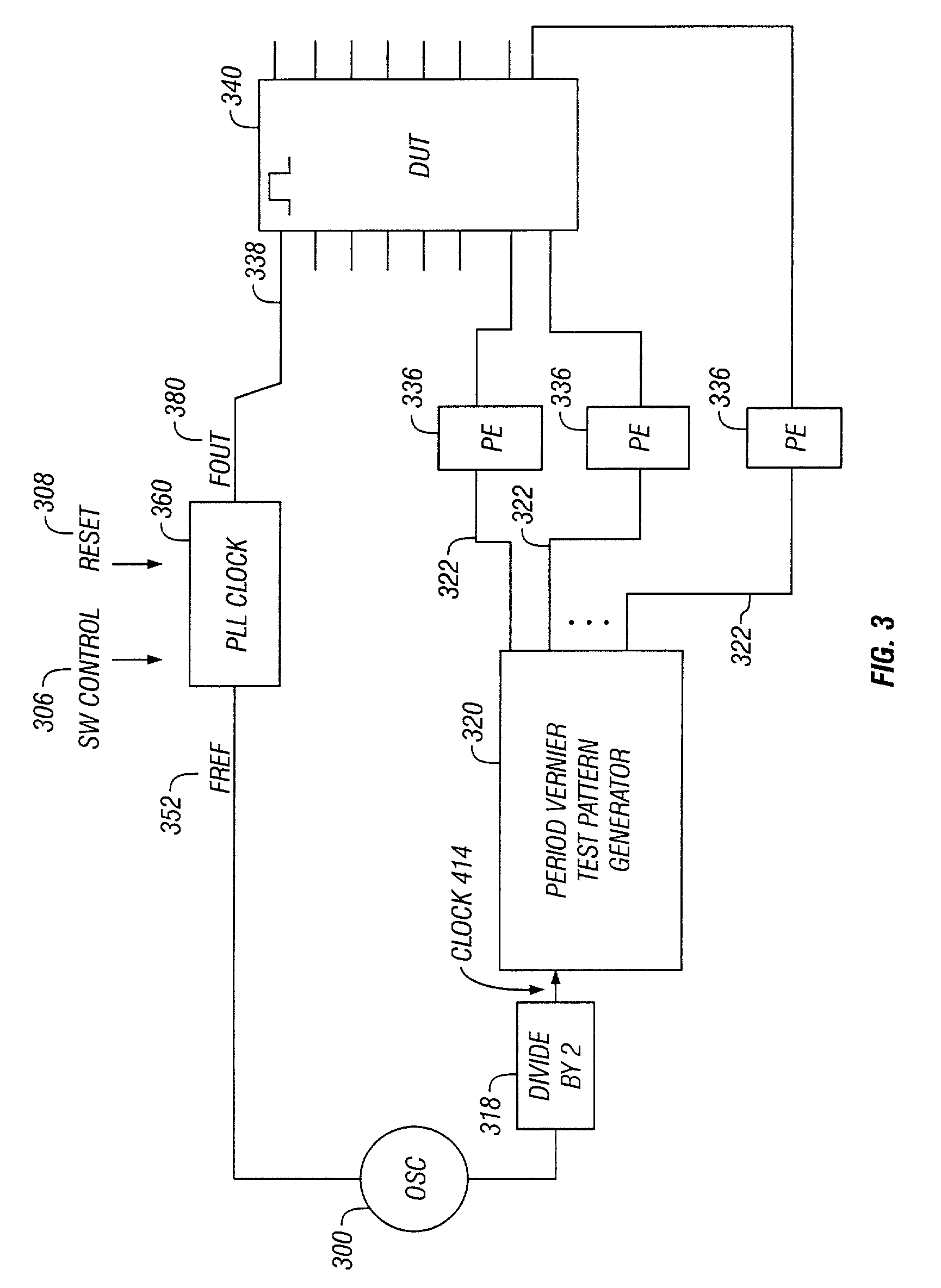
[0028]FIG. 3 is a block diagram of a test system that, by using a period vernier for generating test pattern signals and a PLL-based clock having a range of programmable frequencies for generating clock signals, can improve edge placement accuracy and can provide a clock signal having low period-to-period jitter to a DUT clock input.

[0029]System oscillator (OSC) 300 provides a clock signal to a phase-lock-loop clock (PLL Clock) 360 through input signal Fref 352. The system oscillator 300 also provides a clock signal to a divide-by-2 circuit 318, which divides the clock signal in half. In this particular case, the system oscillator 300 is running at 800 MHz, but other frequencies could be used depending on application and design parameters. The output of the divide-by-2 circuit 318 is the master clock (Clock) 414, which in this case is running at 400 MHz, but other master clock frequencies can be obtained by using a system oscillator running at a different frequency or using a progra...


PUM


Abstract

Generating test signals for a device under test (DUT) involves generating a master reference signal, using a vernier technique to generate test pattern signals based on the master reference signal, generating a test clock signal that is phase-matched with and frequency similar to the test pattern signals by providing the master reference signal as input to a phase-locked loop (PLL) and controlling one or more programmable dividers in the PLL to adjust the test clock signal to be a multiple or sub-multiple of a frequency of the test pattern signals, applying the test clock signal to the clock input pin of the DUT, and applying the test pattern signals to data pins of the DUT. When the frequency of the test pattern signals is changed, the test clock signal frequency may be adjusted to calibrate to the changed frequency of the test pattern signals by re-programming the programmable dividers.

Description

RELATED APPLICATION[0001]This application claims priority to U.S. Provisional Patent Application No. 60 / 277,675, filed Mar. 20, 2001, and to U.S. Provisional Patent Application No. 60 / 277,795, filed Mar. 21, 2001.BACKGROUND[0002]This application relates to test system clocks used to generate test patterns and clock signals for test circuits, such as integrated circuit devices.[0003]Test systems for testing high-speed integrated-circuit devices (i.e., device under test (DUT)), such as microprocessors, have become increasingly sophisticated due to the need for generating precise clock signals and test pattern signals. The clock signals are provided to a DUT's clock input pin and used to run the DUT, while the test pattern signals are used to drive and strobe the DUT's data pins.[0004]Test pattern signals (which are also referred to as “event sequences”) generally include a pattern of events, such as binary values (1s and 0s), and an associated time for the occurrence of each event at ...

Claims


Application Information

Patent Timeline
Patent Type & Authority Patents(United States)
IPC IPC(8): G01R31/28G06F11/00G01R31/00G01R31/317G01R31/3185G01R31/319G01R31/3193G11C29/10G11C29/56
CPCG01R31/31709G01R31/318505G01R31/31917G01R31/31937G11C29/10G11C29/56G01R31/31922G11C2029/0401
Inventor WEST, BURNELL G.RICCA, PAOLO DALLA
Owner SCHLUMBERGER TECH CORP
Why Eureka
Try Eureka