
Windscreen wiper with spray nozzle

Inactive Publication Date: 2006-08-22
ROBERT BOSCH GMBH
View PDF17 Cites 46 Cited by
  • Summary
  • Abstract
  • Description
  • Claims
  • Application Information

AI Technical Summary

Benefits of technology

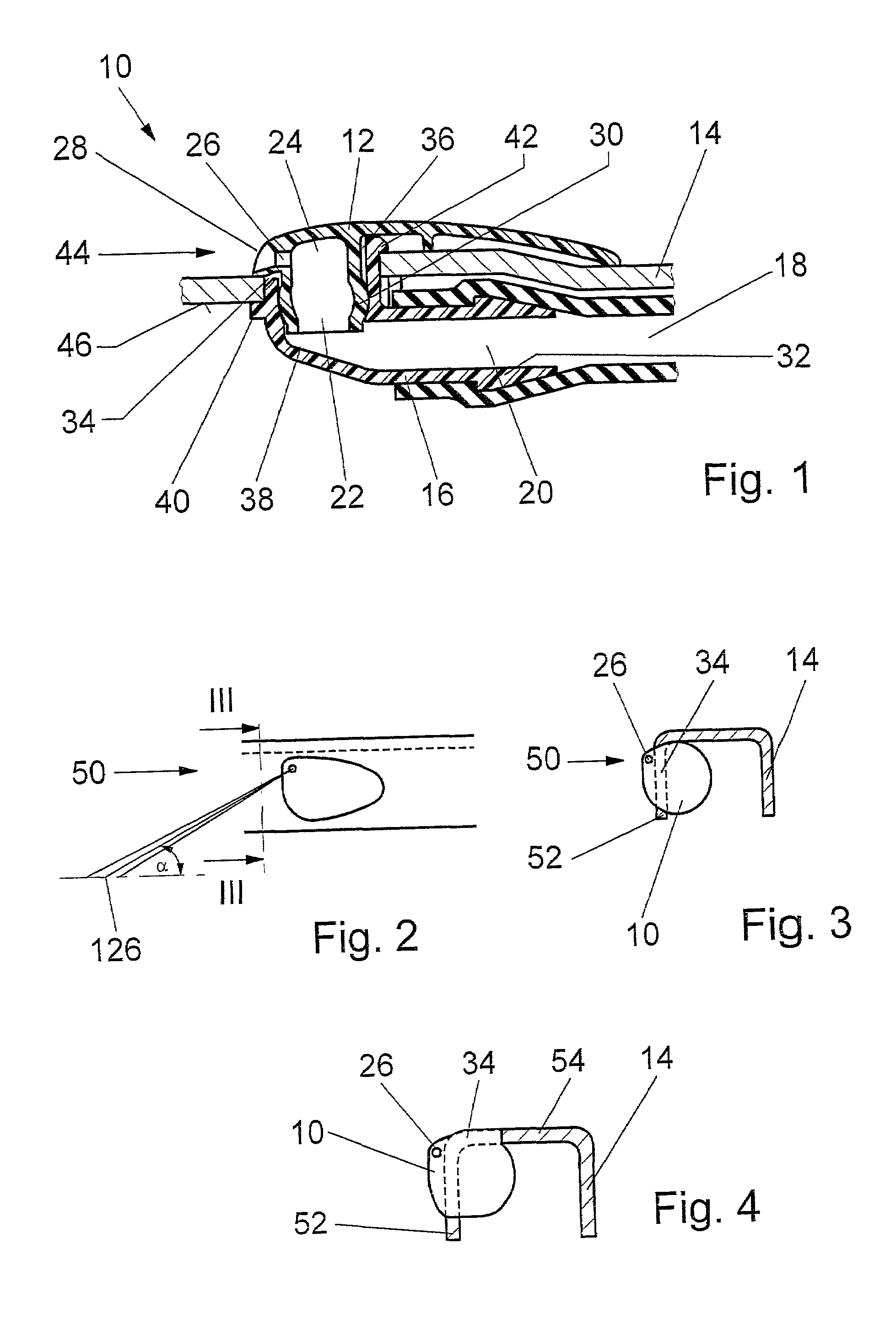
[0009]In one feature of the invention, the housing is retained, for instance clipped, in an opening of the retaining element. A nozzle body with a stub surrounding the spray conduit is inserted from outside into the opening, protruding through the retaining element, of the connecting conduit of the housing. The outer part of the nozzle body has a nozzle opening and covers the housing and the opening of the retaining element. Hence the structural parts can be quickly joined to one another separably, and they can also easily be replaced individually. The spray nozzle protrudes out of the retaining element with only the outer part of the nozzle body, and that part fits smoothly with the contour of the retaining element, so that both visually and in terms of fluidics it is not a hindrance and it causes no noise.
[0018]The heated water improves the cleaning action, so that not only water consumption but especially the consumption of polluting additives can be reduced.

Problems solved by technology

The heating elements require relatively great effort and expense for producing the spray nozzles and great effort and expense for assembly for laying the electric lines and contacting the plugs.
Furthermore, the highly volatile antifreeze agents rapidly evaporate, and the nozzle openings become plugged with the residues.
A disadvantage of such systems is that the effects of weather, especially hail and extreme sunshine, have a major effect on the flexible parts of this arrangement, which are required for spanning the jointed regions between the wiper arm and the wiper blade.
Since short stream lengths result from this arrangement, even at relatively high vehicle speed the relative wind can have only little effect on the distribution of spraying water.

Method used


Image

  • Windscreen wiper with spray nozzle
  • Windscreen wiper with spray nozzle
  • Windscreen wiper with spray nozzle

Examples


Embodiment Construction

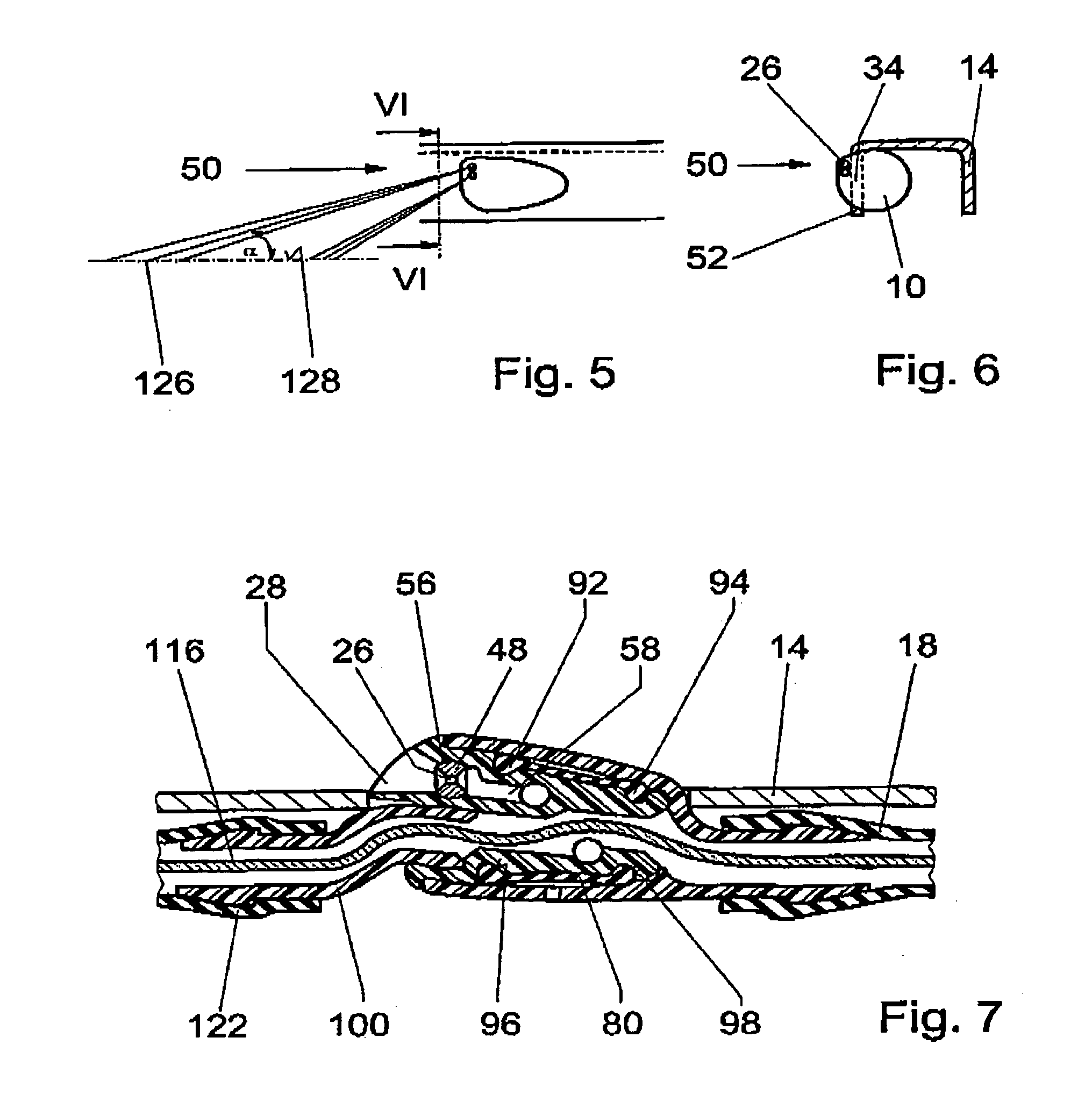
[0032]A spray nozzle 10 is secured to a pivotable part of a wiper arm, not shown in further detail. The pivotable part will hereinafter be called a retaining element 14, and it can be a fastening part, a hinge part and / or a wiper rod connected to the hinge part, or part of a wiper blade.

[0033]The spray nozzle 10 comprises a housing 16, which is separably connected by means of a connection piece 32 via a water line 18 to a water pump 118, which from a supply tank 120 pumps washing water to the spray nozzle 10 (FIG. 12). The housing 16 is made from plastic and surrounds a water conduit 20, which is closed on its free end 38 and from which a connecting conduit 22 branches off. The connecting conduit 22 leads to a spray conduit 24 having a nozzle opening 26. The housing 16 is clipped into an opening 34 of the retaining element 14 and is fixed and retained by means of integrally formed lugs 40 and 42. A nozzle body 12 has a stub 30, which surrounds the spray conduit 24 and with which, vi...


PUM


Abstract

A windshield wiper includes a wiper arm, which is driven via a drive shaft and to which a wiper blade is pivotably connected, in which at least one spray nozzle (10) is disposed on a pivotable part (14), the spray nozzle being composed of a plurality of parts and its housing (16) communicating disconnectably via a water line (18) to a water pump (118). In the housing (16) or in a nozzle body (12) communicating with it, a continuous water conduit (20) connected to the water line (18) is provided, from which a connecting conduit (22) branches off that leads to a spray conduit (24) that is approximately parallel to the water conduit (20) and has a nozzle opening (26), the water conduit (20) being closed on its free end (38).

Description

BACKGROUND OF THE INVENTION[0001]The invention is relates generally to a windshield wiper having a wiper arm, which is driven via a drive shaft and to which a wiper blade is pivotably connected.[0002]Known windshield wipers have a wiper arm, which is made up of a fastening element and a hinge element, which is pivotably connected to it via a swivel joint and has a wiper rod. A hooklike end of the wiper rod engages a suspension box of a wiper blade, which is formed by two side cheeks of a middle bracket and includes a hinge bolt. The hinge thus formed guides the wiper blade over the vehicle window during the swiveling motion. The wiper blade has what is as a rule a multi-member support bracket system, with subordinate brackets pivotably connected to the middle bracket, at least some of which subordinate brackets, with claws on their ends, retain a wiper strip by its head strip. The multi-member support bracket system and spring rails placed in the head strip make it possible during w...

Claims


Application Information

Patent Timeline
IPC IPC(8): B60S1/52B60S1/34B60S1/48B60S1/46B05B1/10
CPCB60S1/522B60S1/46
Inventor ZIMMER, JOACHIM
Owner ROBERT BOSCH GMBH
Learn More