Fuel injector noise mufflers

a fuel injector and noise muffler technology, which is applied in the direction of liquid fuel feeders, machines/engines, mechanical equipment, etc., can solve the problems of destructive interference and substantially reduce and achieve the effect of reducing noise and reducing the main sound pressure wav

Inactive Publication Date: 2006-08-22
DELPHI TECH INC
View PDF19 Cites 26 Cited by
  • Summary
  • Abstract
  • Description
  • Claims
  • Application Information

AI Technical Summary

Benefits of technology

[0003]The present invention addresses the above described need by providing devices and methods that substantially reduce noise caused by the mechanical movement of the fuel injectors in an internal combustion engine. In a first embodiment, a muffler is provided in the socket between the fuel injector and the fuel rail. The inlet and outlet of the muffler are offset such that the sound pressure wave created by the mechanical movement of the injector exits the injector through a first tube, reflects off surfaces of the muffler cavity (socket), and enters the rail through a second tube offset from the first tube. Both tubes are preferably perforated for the addition of other frequency pressure waves into the cavity. The reflections of the various pressure waves in the muffler cavity cause destructive interference and substantially reduce the main sound pressure wave.
[0005]In a third embodiment, an expansion chamber is provided between the fuel injector and fuel rail. The expansion chamber changes the volume of the area through which the fuel passes and acts to substantially reduce the sound pressure wave traveling therethrough. As with the side branch filter, the size of the expansion chamber may be selected and calibrated to the specific frequencies being targeted for reduction or elimination. This embodiment of noise control device and method is able to cover a broader frequency band than the side branch filter.
[0006]In a fourth embodiment, a single perforated tube is associated with a respective fuel injector and extends from its respective fuel injector socket and into the fuel rail. The sound pressure wave emanating from the injector enters the respective socket and perforated tube. The pressure waves are then forced through the tube perforations into the main rail cavity. The refection that occurs due to the volume change reduces the undesired sound pressure wave.

Problems solved by technology

The reflections of the various pressure waves in the muffler cavity cause destructive interference and substantially reduce the main sound pressure wave.

Method used


Image

  • Fuel injector noise mufflers
  • Fuel injector noise mufflers
  • Fuel injector noise mufflers

Examples


second embodiment

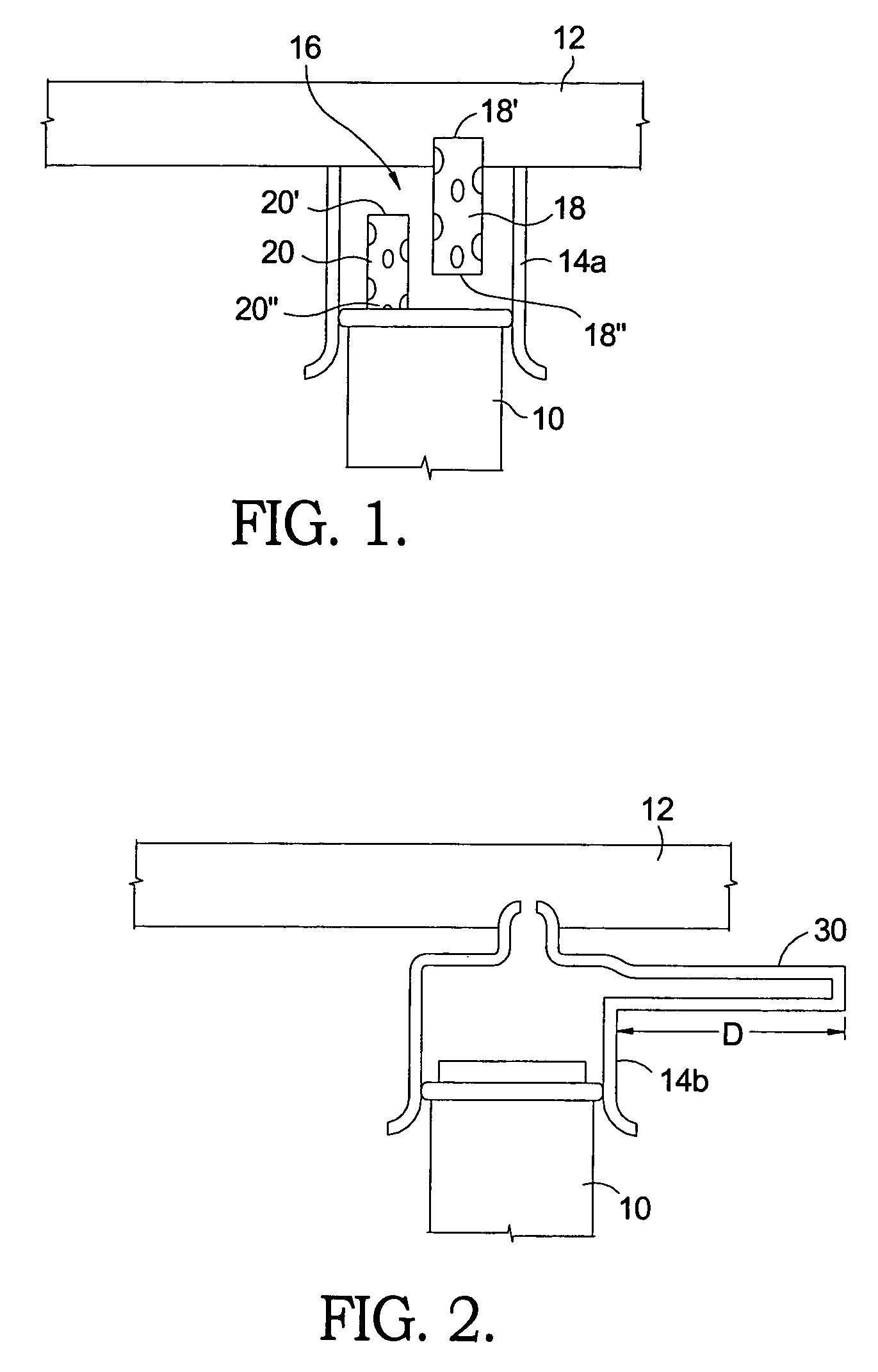
[0015]the invention is seen in FIG. 2 wherein a side branch filter 30 extends from modified socket 14b. Side branch filter 30 has a length “D” that is ¼ the wavelength of the frequency of the pressure wave emanating from injector 10. According to the known equation:

[0016]D=λ4=V4⁢F(Eq.⁢1)

where[0017]λ=wavelength[0018]V=Velocity of Sound in the Fluid and[0019]F=Noise Frequency,

a side branch filter having a length D that is ¼ of the propagating wave frequency will produce a reflected wave that is 180° out of phase with the propagated wave, thereby canceling the propagated wave and reducing noise. For example, if V=1140 m / s and the undesirable frequency is 5000 Hz, then D=57 mm.

third embodiment

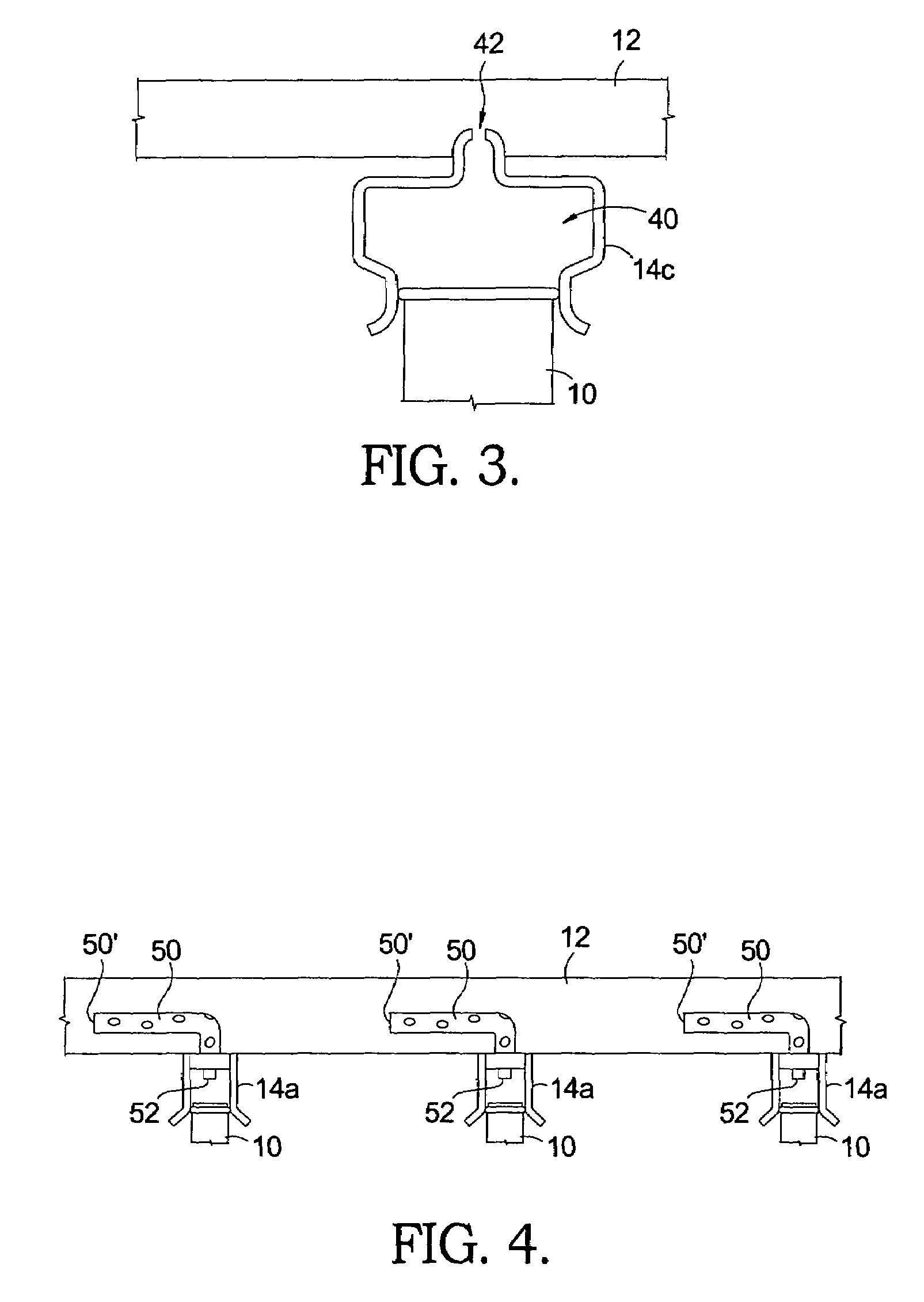
[0020]the invention is seen in FIG. 3 wherein a modified socket 14c defining an expansion chamber 40 is provided between injector 10 and the fluid port 42 communicating with fuel rail 12. An expansion chamber changes the volume of a flow path which causes sound reflection that reduces the originating pressure wave. The calculation of the length of the expansion chamber 40 follows the same procedure as outlined above for the side branch filter, however, this method of sound attenuation is able to target a larger frequency range than the side branch filter.

fourth embodiment

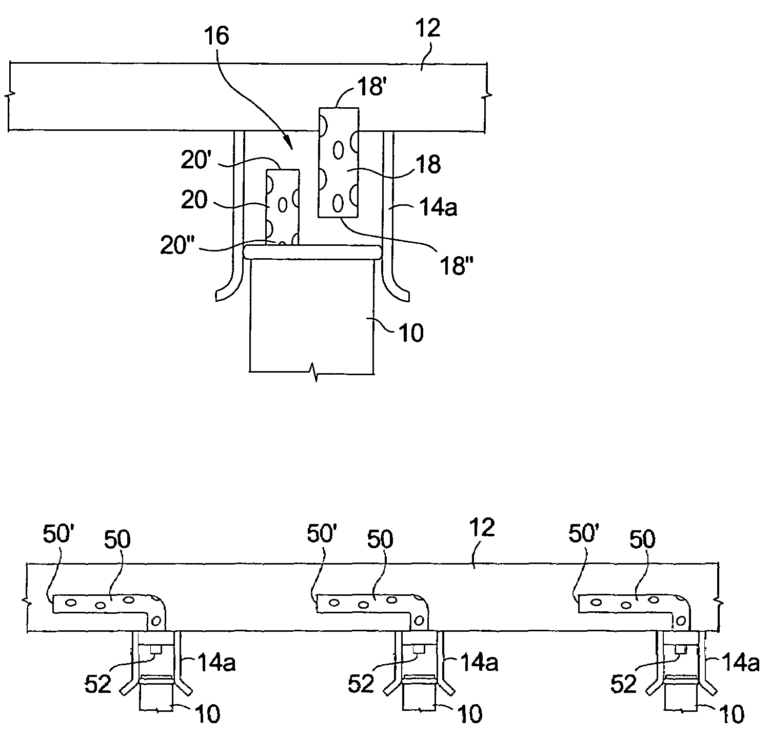
[0021]FIG. 4 shows yet the invention wherein a perforated tube 50 extends from a respective socket 14a and injector port 52, into the fuel rail 12, terminating at a closed end 50′. In the preferred embodiment, the portion of the tube including closed end 50′ extends substantially parallel to fuel rail 12 and may or may not be coaxial therewith. The pressure wave originating from injector 12 travels through the perforated tube 50 and is forced through the tube perforations into the main rail cavity. The refection that occurs due to the volume change reduces the undesired sound pressure wave.


PUM


Abstract

Several embodiments of noise reduction apparatus for a fuel injector are disclosed and include perforated tubes, side branch filters and expansion chambers strategically located between a respective injector and the fuel rail to target and reduce high frequency noise generated by the mechanical movement of the fuel injector.

Description

TECHNICAL FIELD[0001]The present invention relates to noise control of fuel injectors in an internal combustion engine. More particularly, the present invention relates to various devices and methods for reducing or eliminating noise caused by the mechanical movement of the fuel injectors.BACKGROUND OF THE INVENTION[0002]Fuel injector systems, which deliver fuel to the combustion chamber of internal combustion engines, have been around for many years. The fuel injection system draws fuel from a fuel tank, through tubing, to a fuel rail mounted adjacent the cylinder bank or banks of the engine. The fuel injectors, typically one for each cylinder, extend from the fuel rail to inject the fuel in proximity to an intake valve for a respective cylinder. The fuel injectors are electro-mechanical devices which have moving parts that deliver the fuel in precise amounts and times to the respective cylinder. While the engine is running, the fuel injectors are essentially constantly working. No...

Claims


Application Information

Patent Timeline
Patent Type & Authority Patents(United States)
IPC IPC(8): F02M63/00F02M63/02
CPCF02M55/04F02M69/465F02M2200/31F02M2200/30
Inventor POTTER, DUANE E.BRAUN, CHARLES W.
Owner DELPHI TECH INC
Why Eureka
Try Eureka