Intravascular dilatation implant with a deflector

a dilatation implant and deflector technology, applied in the field of intravascular dilatation implants, can solve the problems of not solving the problem completely, the rate of restlessness is reduced, etc., and achieve the effect of increasing the shear stress and promoting the decrease of the restlessness ra

Inactive Publication Date: 2006-08-22
ECOLE POLYTECHNIQUE FEDERALE DE LAUSANNE (EPFL)
View PDF19 Cites 11 Cited by
  • Summary
  • Abstract
  • Description
  • Claims
  • Application Information

AI Technical Summary

Problems solved by technology

These devices, although having contributed to the decrease in the rate of restenosis, have nevertheless not totally solved the problem.

Method used


Image

  • Intravascular dilatation implant with a deflector
  • Intravascular dilatation implant with a deflector
  • Intravascular dilatation implant with a deflector

Examples


Embodiment Construction

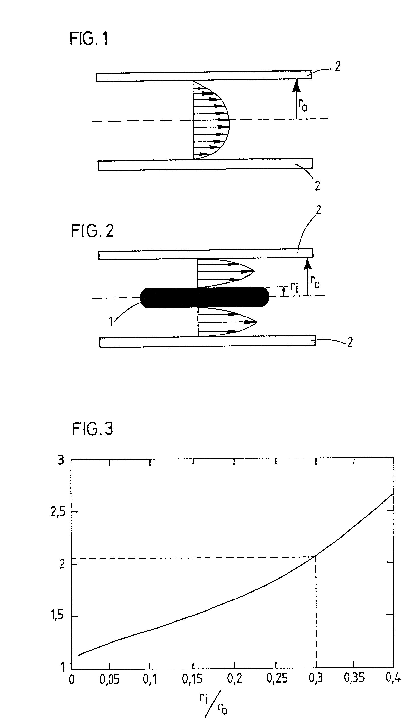
[0011]Scientific studies, confirmed by critical observations, have shown that restenosis is attributed to a cellular proliferation of the intimal tissue, called intimal hyperplasia. The mechanisms of this reaction are not entirely understood at present. However, it is certain that the prevention or reduction of intimal hyperplasia constitutes a key element in the success of the treatment of stenosis or arterial occlusions. It has been determined in animals that intimal hyperplasia is reduced when the blood flow is high in the vessel in question. On the other hand, when this flow rate is low, the intimal layer increases. The same determination has been made by cardiologists and radiologists, who have observed that following an angioplasty, the stents remain open if the flow rate is high and that they have the tendency to plug in the presence of a low blood flow rate. There exists as a result a certain relationship between the blood flow rate and intimal hyperplasia. This fact is conf...


PUM

PropertyMeasurementUnit
blood flow shear rateaaaaaaaaaa
diameteraaaaaaaaaa
shear stressesaaaaaaaaaa

Abstract

An intravascular dilator includes a central body acting as deflector o the blood flow to increase the value of shear stress to the artery wall. Flexible spires soldered to the deflector are radially extensible from a first diameter substantially equal to the deflector diameter to a second diameter greater than the artery diameter, the spires rest against the artery internal wall in operative position.

Description

BACKGROUND OF THE INVENTION[0001]The present invention relates to an intravascular implant permitting radial dilatation of the arterial walls. These implants or dilatators are known as “stents” in the field of transluminal angioplasty. Transluminal angioplasty consists in treating diseased regions of the arterial system by the introduction of apparatus, particularly catheters, along natural routes. This permits localized intervention without having to have recourse to conventional surgical interventions which have, because of their seriousness, numerous drawbacks for the patients. This technique is particularly used when a constriction or stenosis of the arteries is diagnosed. There is then introduced through the femoral artery a catheter provided at its distal end with an inflatable angioplasty balloon. This catheter is then pushed and guided, with radioscopic monitoring, through the arterial system to the diseased region of the artery. Once this region is reached, the balloon is i...

Claims


Application Information

Patent Timeline
Patent Type & Authority Patents(United States)
IPC IPC(8): A61F2/86A61F2/00A61F2/01A61F2/02A61F2/06
CPCA61F2/01A61F2/86A61F2002/068A61F2210/0004A61F2210/0095A61F2230/0091Y10S623/903A61F2002/016A61F2230/0006A61F2230/008A61F2250/0067
Inventor STERGIOPULOS, NIKOLAOS
Owner ECOLE POLYTECHNIQUE FEDERALE DE LAUSANNE (EPFL)
Why Eureka
Try Eureka