Multi-tunable microelectromechanical system (MEMS) resonators

Inactive Publication Date: 2006-08-22
NAT TECH & ENG SOLUTIONS OF SANDIA LLC
View PDF18 Cites 18 Cited by
  • Summary
  • Abstract
  • Description
  • Claims
  • Application Information

AI Technical Summary

Benefits of technology

[0009]It is a further object to provide a MEMS resonator and a method for tuning a MEMS resonator

Problems solved by technology

However, prior MEMS resonators have several limitations.
One limitation is that prior MEMS resonators may only have resonant frequency changed in one direction, i.e. an increase the resonant frequency, and do not have the capability to have resonant frequencies both increased and decreased from the natural resonant frequency.
In addition, another limitation of prior MEMS resonators is that the bandwidth Q is inadvertently changed and redu

Method used


Image

  • Multi-tunable microelectromechanical system (MEMS) resonators
  • Multi-tunable microelectromechanical system (MEMS) resonators
  • Multi-tunable microelectromechanical system (MEMS) resonators

Examples


example 1

[0073]Using the parameters set forth in Table 1 and Table 2, the following tuning trends for BW and f* are shown in FIGS. 5-7. The value of RL in equation 2 is defined so that μ=0.1.

[0074]

TABLE 1Micro-Mechanical Beam SystemDescription of ParametersValues of the Parameters Length of BeamL = 450 micronsWidth of Beamb = 40 micronsThickness of Beamh = 2 micronsDensity of Polysilicon Materialρ = 2.33e + 03 Kg / m3Volume of BeamLbh = 3.6e − 14 m3Mass of Beamm = 8.388e − 11 KgYoung's ModulusE = 1.60e + 11 Newtons / m2Beam Elastic “spring” Constantk = 3.37 Newtons / mBeam {square root over (k / m)} Constantω0 = {square root over (k / m)} = 200,476 rad / secResonant Frequency of Beamƒ0 = ω0 / 2π = 31,906.8 HzMechanical Damping Constantζ = 0.0001

[0075]

TABLE 2Capacitor-Based CircuitDescription of ParametersValues of the ParametersCapacitor Area (200 microns × 40 microns)A = 8.0e − 09 m2Permittivity of Free Spaceε0 = 8.854e − 12 farad / mDistance Between Parallel-Plate Condenserd0 = 2 micronsCapacitance for P...

example 2

[0115]Using the parameters set forth above in Tables 1 and 2, with one exception, the following tuning trends for BW and f* are given in FIGS. 5, &8-9. The exception in Table 2 is that value of RL in equation 2 is defined so that μ=10 which implies that RL is 100 times higher in this example.

[0116]FIG. 5 is a graph of the relationship between V0 and λ for a vibratory device constructed in accordance with an embodiment of the present invention.

[0117]FIG. 8 is a graph of the relationship between BW and λ for a vibratory device constructed in accordance with an embodiment of the present invention. The bandwidth BW increases up to 30 times for small values of λ(μ=10).

[0118]FIG. 9 is a graph of the relationship between a change in resonant frequent and λ for a vibratory device constructed in accordance with an embodiment of the present invention. The resonant frequency f* decreases only up to 0.03% for small values of λ(μ=10).

[0119]For values of μ much larger than 1.0 there is a much sma...

example 3

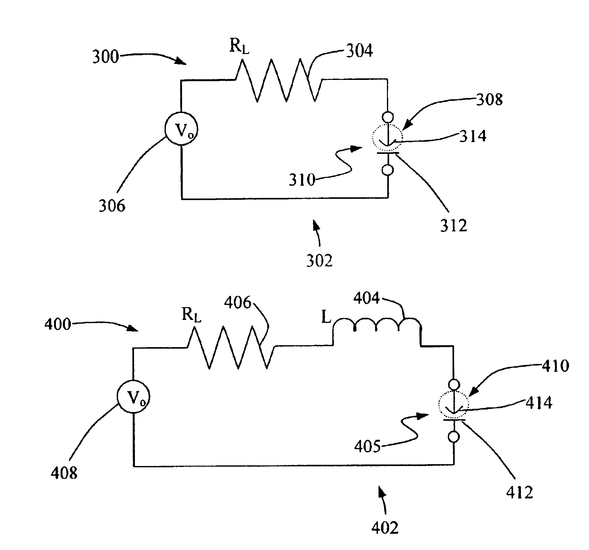
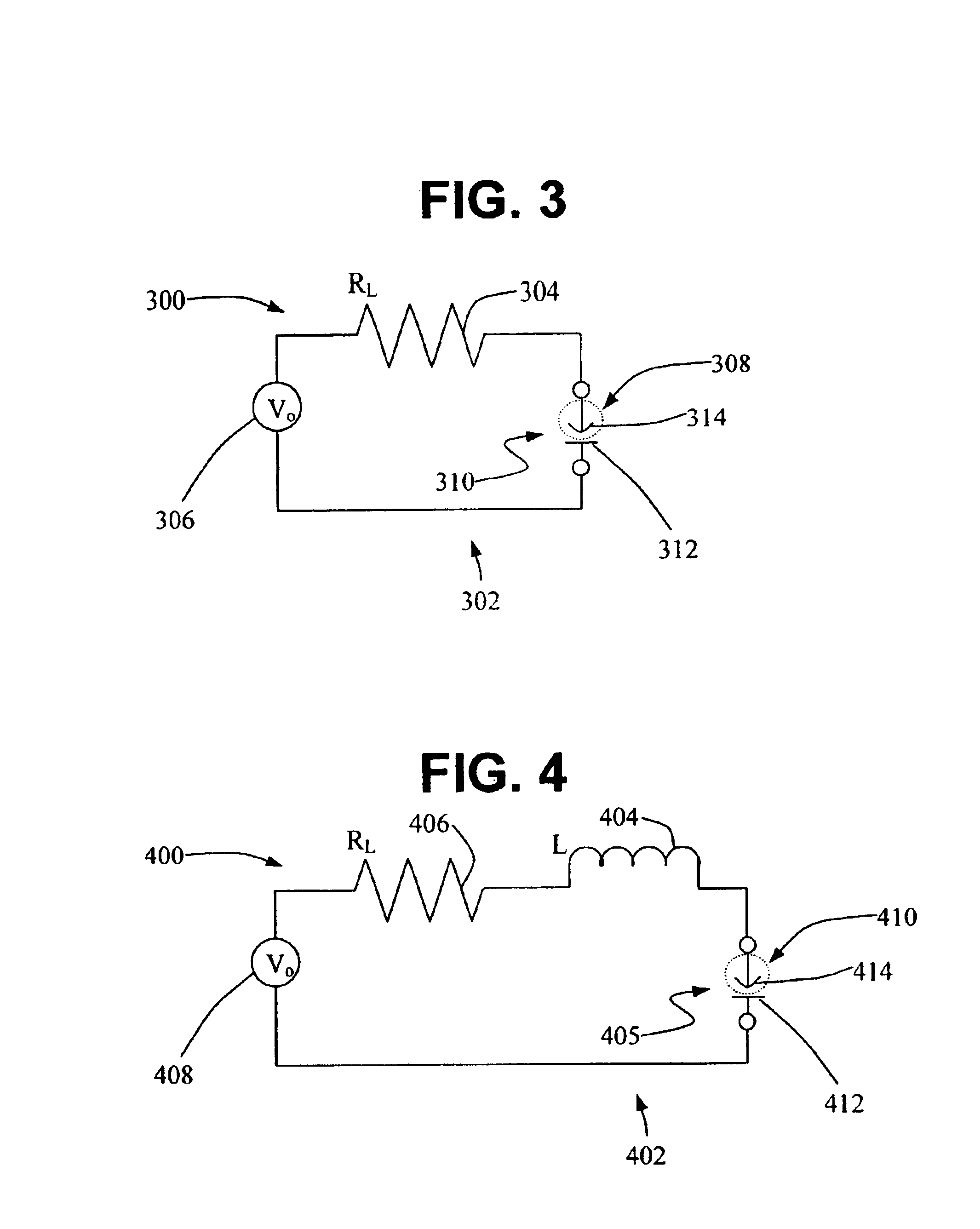
[0120]For the purpose of improving the capability to tune the resonant frequency of a micro-mechanical resonator, this example adds a self-inductance element L to a vibratory device of the present invention having a capacitor-based circuit with load resistor RL and voltage source V0. The tuning is described in terms of three non-dimensional parameters μ, γ, and δ that depend on RL, L, and V0. Using the values of the parameters as set forth in Tables 3 and 4, the following tuning trends for BW and f* are presented in FIGS. 10-14. The value of RL in equation 57 is defined so that μ=0.1. μ=ω0⁢c0⁢RL(1-λ)(57)

[0121]The value L of in equation 58 is defined so that δ varies in the range −0.1≦δ≦+0.1. γ=1+δ=ω0⁢c0⁡(L⁢ ⁢ω0)(1-λ)(58)

[0122]The voltage source V0 is determined so that 0≦λ≦0.001, as shown in equation 59. V02=λ⁡(1-λ)2⁢2⁢kd02c0(59)

[0123]

TABLE 3Micro-Mechanical Beam SystemDescription of ParametersValues of the Parameters Length of BeamL = 450 micronsWidth of Beamb = 40 micronsThickness...


PUM


Abstract

A method for tuning a vibratory device including a cantilevered resonator comprising the steps of increasing a voltage V0 supplied to the vibratory device to thereby increase the bandwidth of the vibratory device; and keeping the resonant frequency of the vibratory device at substantially that natural frequency of the cantilevered resonator, wherein the vibratory device comprises: a capacitor including a movable plate and a fixed plate spaced from each other, the movable plate being part of the cantilevered resonator; a voltage source connected to the capacitor for providing voltage V0 across the capacitor to produce an attractive force between movable plate and fixed plate; a circuit connecting the voltage source to the capacitor; and a load resistor in said circuit having a resistance RL satisfying the following equation: μ=ω0c0RL(1-λ)
where: μ is at least 10; ω0 is the beam constant for the cantilevered resonator; c0 is the capacitance for the capacitor; and λ is the voltage dependent coupling parameter for voltage V0.

Description

GOVERNMENT INTEREST STATEMENT[0001]The United States Government has rights in this invention pursuant to Contract No. DE-AC04-94AL85000 between the United States Department of Energy and the Sandia Corporation for the management and operation of Sandia National Laboratories.BACKGROUND OF THE INVENTION[0002]1. Field of the Invention[0003]The present invention relates to a tunable MEMS resonator and a method for actively tuning a MEMS resonator.[0004]2. Description of the Prior Art[0005]Microelectromechnical systems (MEMS) are miniaturized devices that provide low power consumption, and high frequency and greater sensitivity. MEMS components may be etched from a single material, such as crystal silicon. Prior devices have incorporated the technology of MEMS to resonators.[0006]However, prior MEMS resonators have several limitations. One limitation is that prior MEMS resonators may only have resonant frequency changed in one direction, i.e. an increase the resonant frequency, and do no...

Claims


Application Information

Patent Timeline
IPC IPC(8): H03H9/46
CPCH03H9/02409
Inventor STALFORD, HAROLD L.BUTLER, MICHAEL A.SCHUBERT, W. KENT
Owner NAT TECH & ENG SOLUTIONS OF SANDIA LLC
Why Eureka
Try Eureka