Image display device, rear projection type screen used in image display device, Fresnel lens sheet, and method of making Fresnel lens sheet

a technology of image display device and lens, which is applied in the direction of instruments, mountings, projectors, etc., can solve the problems of large loss, limited widening of lens field angle, image display device darkening at right and left upper end, etc., and achieve the effect of reducing the thickness of image display devi

Inactive Publication Date: 2006-08-22
MAXELL HLDG LTD
View PDF7 Cites 4 Cited by
  • Summary
  • Abstract
  • Description
  • Claims
  • Application Information

AI Technical Summary

Benefits of technology

[0005]Problems to be solved by the present invention will now be described with reference to FIGS. 8 and 9. When image display devices having the same screen size are compared with each other, the smaller the depth, the more advantages in point of weight, cost and installation space. A reflecting mirror 54 is used for decreasing the depth of an image display device in FIGS. 8 and 9. Making wider the field angle of a projection lens 52 is also a means for decreasing the depth. However, a limit is encountered in widening the field angle of the lens. Suppose that an aspect ratio is 16:9 and a diagonal length is 65 inches. If the projection distance is set at 700 mm or less, an image generation source 51 and the projection lens 52 interfere with projection light. Consequently, a shadow area forms on a rear projection type screen 53. Thus, assume that an attempt is made to attain the reduction of thickness by only widening of the field angle of the projection lens 52; a limit is encountered at a depth of 400 mm of an optical system in the case where an aspect ratio is 16:9 and a diagonal length is 65 inches. Incidentally, a depth of the image display device is 450 mm in this case. In FIG. 8, an optical axis center of the projection lens 52 and the center of the rear projection type screen 53 are aligned with each other and an optical axis and the screen are set perpendicularly to each other. However, by setting the optical axis center of the projection lens 52 in the vicinity of a lower end of the rear projection type screen 53, the image generation source 51 and the projection lens 52 no longer interfere with projection light. This holds true even if the projection distance is set at 700 mm or less. The rear projection type screen illustrated in FIG. 9 is 16:9 in aspect ratio and 65 inches in diagonal length as in FIG. 8. However, the optical axis center of the projection lens 52 is made coincident with the lower end of the screen 53 and the projection distance is set at 500 mm. According to the arrangement illustrated in FIG. 9, the depth of the optical system is 300 mm (the depth of the image display device is 350 mm). Thus, it is possible to attain a further reduction of thickness.
[0006]As described above, thickness of the image display device can be reduced as follows. First, shorten the projection distance of the projection lens 52. Then, set the optical axis center of the projection lens 52 at a position near the lower end of the rear projection type screen 53. In this case, however, the following problems newly arise.
[0009]The present invention has been accomplished in view of the above-mentioned problems. It is an object of the invention to provide a technique suitable for shortening the depth of an image display device. It is another object of the present invention to provide a technique suitable for shortening the depth of an image display device without greatly impairing the quality (brightness) of an image displayed on a screen.
[0018]According to the present invention, it is possible to reduce the thickness of the image display device. Particularly, the thickness of the image display device can be reduced without greatly impairing the quality, e.g., brightness, of the image displayed on the screen.

Problems solved by technology

However, a limit is encountered in widening the field angle of the lens.
In this case, however, the following problems newly arise.
If the thickness of the image display device is further reduced, the loss becomes larger rapidly.
This causes the problem that the image display device becomes dark at right and left upper end portions of the screen.
Consequently, it causes the problem that efficiency becomes lower and that a middle-area image (a doughnut-like area on the screen), which is an important image area, becomes dark.

Method used


Image

  • Image display device, rear projection type screen used in image display device, Fresnel lens sheet, and method of making Fresnel lens sheet
  • Image display device, rear projection type screen used in image display device, Fresnel lens sheet, and method of making Fresnel lens sheet
  • Image display device, rear projection type screen used in image display device, Fresnel lens sheet, and method of making Fresnel lens sheet

Examples


first embodiment

[0040]An image display device according to a first embodiment of the present invention will be described in detail hereinunder with reference to the accompanying drawings.

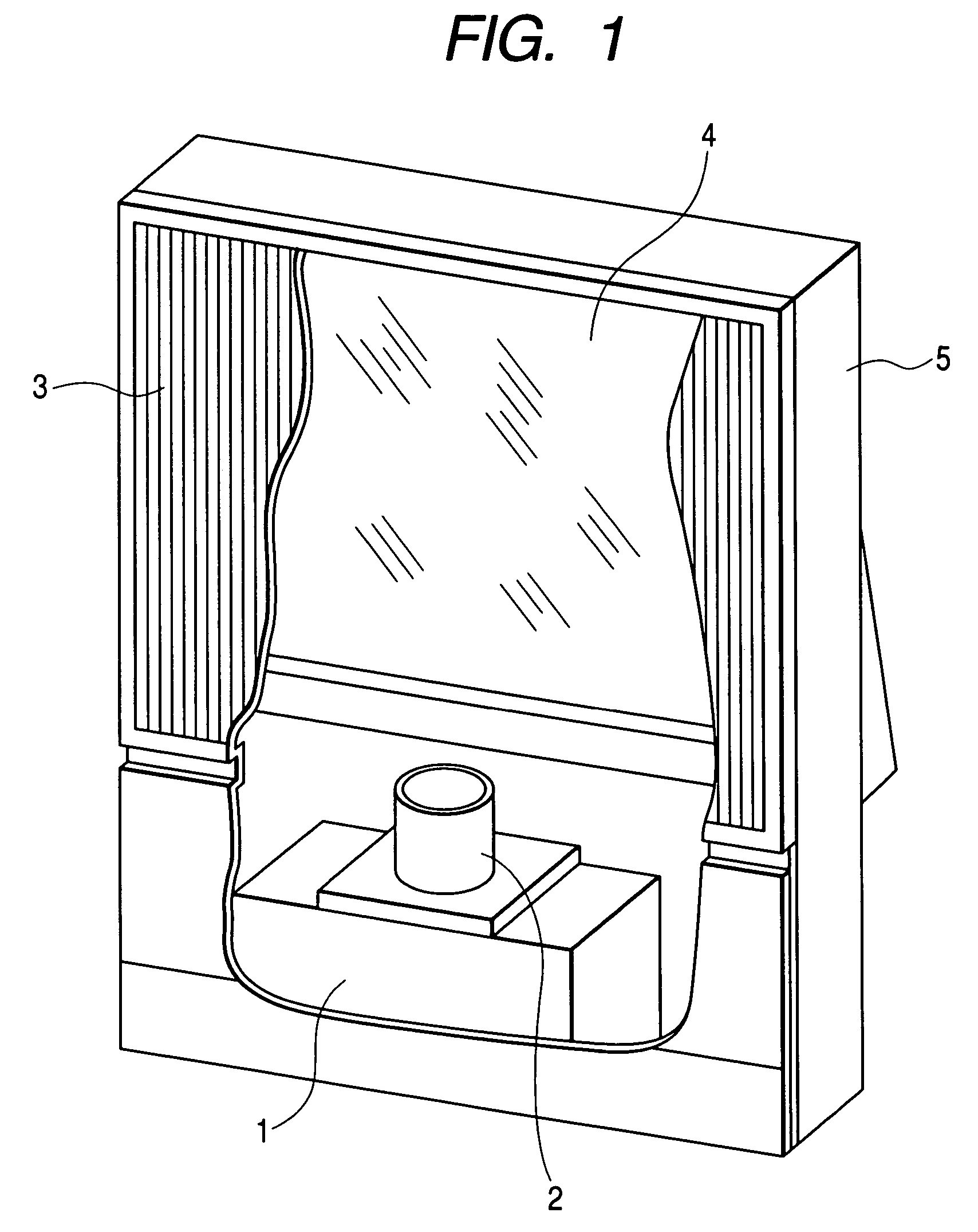
[0041]FIG. 1 is a partially sectional perspective view of the image display device. An image generation source 1 includes a projection type cathode-ray tube, a reflection or transmission type liquid crystal panel, and an image modulator such as a display element provided with a plurality of very small mirrors. The image generation source 1 displays a small-sized image. A projection lens 2 projects the image onto a rear projection type screen 3. Since the projection distance is generally long, a reflecting mirror 4 is disposed in a related optical path for diminishing the depth of the image display device. These components are fixed at respective predetermined positions in the interior of a case 5.

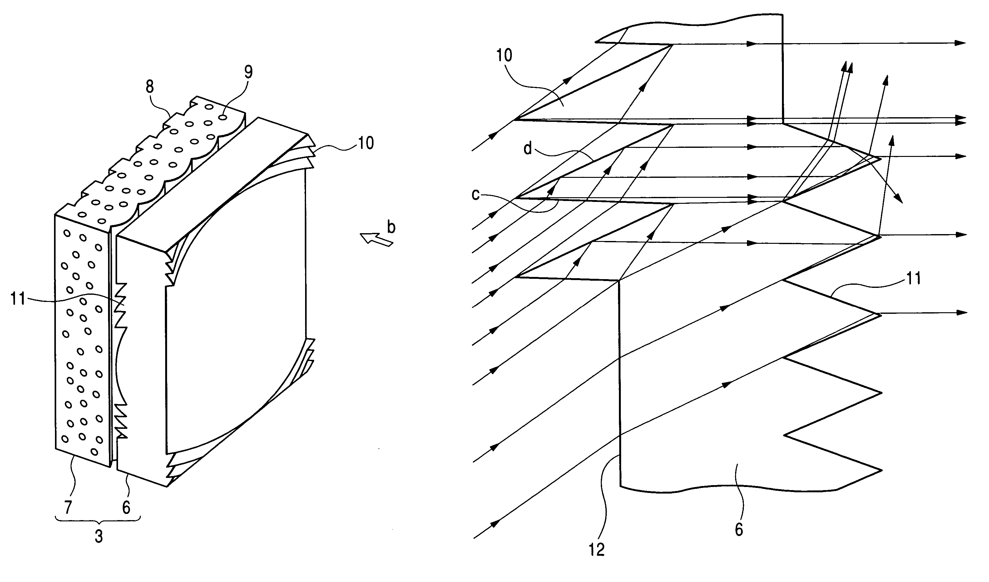
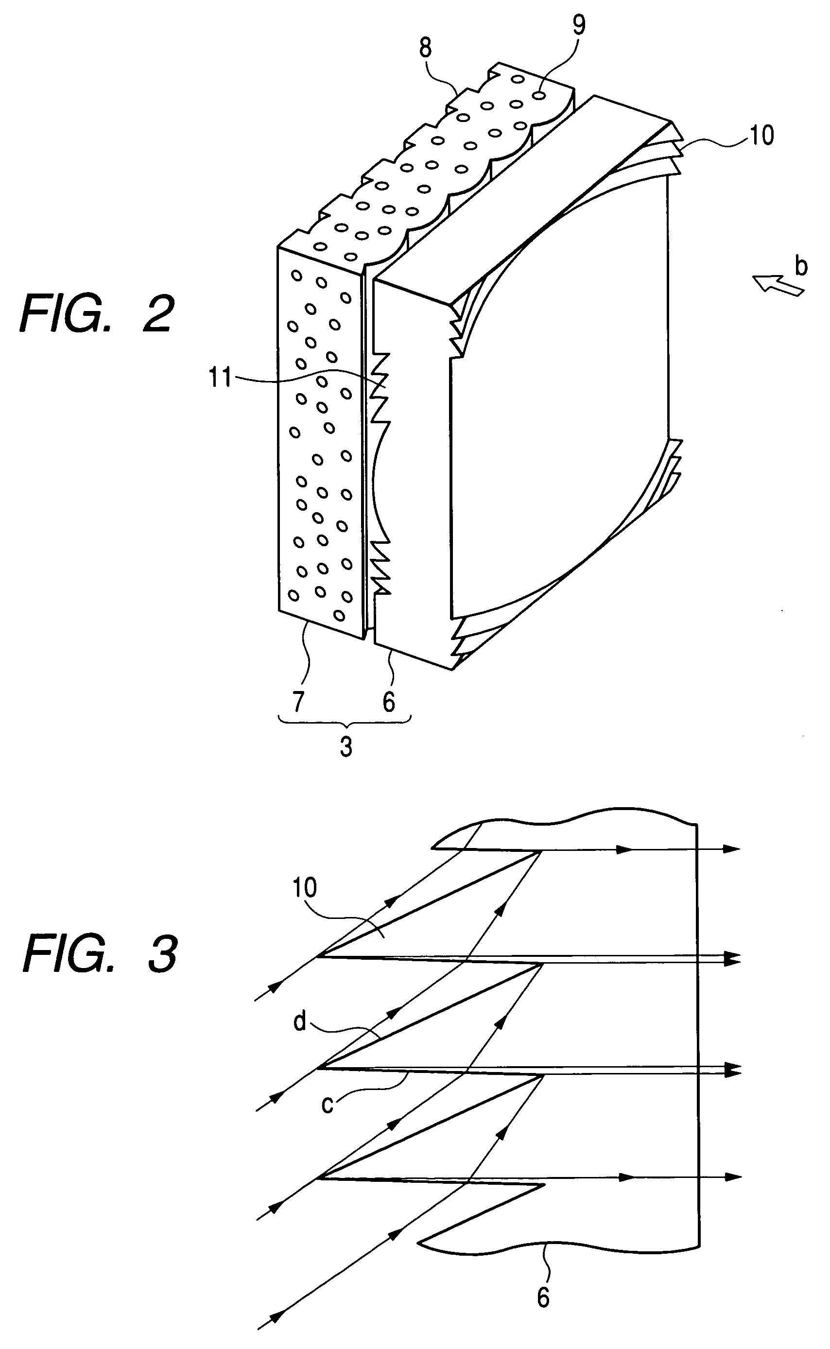
[0042]FIG. 2 is a schematic diagram showing the structure of the rear projection type screen 3 used in the first embodim...

second embodiment

[0053]A second embodiment of the present invention will be described below with reference to the accompanying drawings.

[0054]FIG. 11 is a schematic diagram showing the structure of a rear projection type screen 3 according to the second embodiment. An enlarged projection image (not shown) projected in the direction of arrow b is converted to light which is substantially parallel or light which somewhat faces inwards while passing through a Fresnel lens 6. Then, the converted light is incident on a lenticular lens sheet 7. As shown in the same figure, the lenticular lens sheet 7 has a shape such that plural lenticular lenses having a longitudinal direction vertically of the screen are arranged horizontally of the screen. The lenticular lens sheet 7 functions to diffuse the image light horizontally of the screen. Black stripes 8 extending vertically of the screen are formed on an exit surface of the lenticular lens sheet 7 to absorb extraneous light which is incident from the exit sid...


PUM


Abstract

A total reflecting prism portion is formed on an image generation source side of a Fresnel lens sheet which constitutes a rear projection type screen. The total reflecting prism portion is formed in an area in which the angle of incidence of a projection image projected from an optical part on the Fresnel lens sheet is at least about 40·. The total reflecting prism portion causes incident light to be outputted as output light at a predetermined output angle by a total reflection phenomenon after a first refraction phenomenon. A refracting prism portion is formed on an image monitoring side of the Fresnel lens sheet. The refracting prism portion is formed in an area opposed to the portion where the total reflecting prism portion is not formed. The refracting prism portion causes incident light to be outputted as output light at a predetermined output angle by a second refraction phenomenon.

Description

CLAIM OF PRIORITY[0001]The present application claims priority from Japanese application serial no. P2003-322430, filed on Sep. 16, 2003, and Japanese application serial no. P2003-308198, filed on Sep. 1, 2003, the contents of which are hereby incorporated by reference into this application.BACKGROUND OF THE INVENTION[0002]The present invention relates to an image display device for projecting and displaying an image from an image generation source on a larger scale onto a rear projection type screen. The invention also relates to the rear projection type screen used in the image display device, a Fresnel lens sheet used in the screen, and a method of making the Fresnel lens sheet.[0003]An image display device which enlarges, using a projection lens, an image displayed on a small-sized image generation source and projects the image onto a rear projection type screen has recently been improved remarkably in image quality. Incidentally, a cathode-ray tube or a liquid crystal display m...

Claims


Application Information

Patent Timeline
Patent Type & Authority Patents(United States)
IPC IPC(8): G03B21/60G02B3/08G02B5/04G03B21/28G03B21/62
CPCG03B21/60
Inventor YOSHIKAWA, HIROKIOHISHI, TETSUHIRATA, KOJIIMAFUKU, DAISUKE
Owner MAXELL HLDG LTD
Why Eureka
Try Eureka